Industries like the prescription drugs, food process, agriculture, chemical, and cement producers need industrial blowers to get rid of fine particulates from the air. This theory does not like angles of exactly 90. it is entirely up to you as to how many blades you use in your impeller. Therefore, having achieved the design requirements, the designer should then proceed to optimise operational efficiency. Like all theories it requires you to follow a few basic rules. >6 Blades: A general rule for large aspect ratio impellers ( > 0.75) is to set the straight-line distance between the internal tips (toes) of adjacent blades approximately equal to the depth (radial height) of each blade. It is important to remember the following when designing a fan using the Axial and/or Centrifugal calculation options in our fan calculator:
There are a number of fan types: impeller, axial, centrifugal, Sirocco, etc. 5) If you are getting negative results, this simply means that your head losses are greater than the head generated. 0000010331 00000 n
If you need to include losses in addition to the efficiency of the fan () you can incorporate them by multiplying the expected additional losses by the efficiency factor and entering the modified value for in the input data, Q is the mass flow rate of gas through the fan, Q is the mole flow rate of gas through the fan, v is linear velocity of the gas through the outlet aperture, and are the input and output densities of the gas (respectively) passing through the fan, p is the velocity pressure of the gas passing through the fan, i.e. Please correct the marked field(s) below. One normal axial fan operating at maximum efficiency can achieve a velocity pressure (p) of up to 0.5psi (3,500N/m).

I.e. Within limits, and excluding efficiencies and losses, almost any throughput can be achieved with any of the configurations available.
0000002628 00000 n
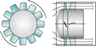
centrifugal axial 
It is important to ensure that the impeller aspect ratio and diffuser inlet area is always larger than this to minimise frictional loss. 2) play with the outside tip angle until you achieve reasonable results,
%
fan axial fans vane flow figure overloading non cibse ventilation ducted module systems cibsejournal source 
However, the flow rate in wide high aspect ratio impellers can be improved by matching the shape of the input orifice to that of the impeller's cross-section, The radial depth of a medium aspect ratio (0.5<<0.75) impeller is relatively high compared with its OD.
For example; Fans does not consider the manufacturing quality of the impeller casing, nor does it consider internal bends or deformations affecting the flow-path. Such impellers provide greater flow rates but reduced pressure potential, Centrifugal fans are normally fitted with impeller aspect ratios greater than 0.5, Axial fans are normally fitted with impeller aspect ratios less than 0.5 (where flow is of greater importance than pressure). Differences such as efficiency or flow rate occur in the type of fan due to particular design advantages that favour one characteristic over another.
This will ensure that the flow and pressure expected from your fan will be similar to your impeller. v and v: the circular speed of the inlet and outlet edges of the blade will be the same for axial fans and different for centrifugal fans
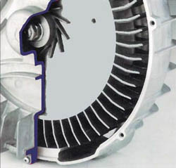
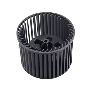
Airflow through the impeller is generated by rotating profiled blades (Fig 1) in a cowling that cut into the air at their inlet tip pushing the air back along the blade and, in the case of centrifugal fans, also from centrifugal forces generating a partial vacuum on the inlet side of the fan due to the entrained air being thrown outwards according the relationship a = v/r. This problem can be overcome simply by altering the outlet angle to 89.99. In order to improve the airflow efficiency of a fan, you need to minimise the losses (L, L, L) and to do this you need to optimise the size and shape of the its blades. 0000003790 00000 n
Saturated air contains wet or gases. ?Rji~fhx*tbqIx/)FTp`F0of"3R
7v9oN'PWN6JUv6>0R7F. 0000011380 00000 n

impeller speed: N = 2685 {RPM}
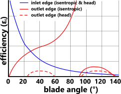
H is the pressure-head of the fan after removing the effect of the operational losses (L, L, L), is the efficiency of the airflow through the fan based upon the loss of head (excluding mechanical efficiency), is the efficiency of the airflow through the fan based upon the loss of head, ignoring loss due to inlet shock (L) (excluding mechanical efficiency), is the isentropic efficiency of the airflow through the fan, v is the absolute velocity of the air at the inlet edge of the blades, v is the absolute velocity of the air at the outlet edge of the blades, v is the axial (AXIAL FANS) or radial (CENTRIFUGAL FANS) velocity of the air at the inlet edge of the blades. the lower the air resistance, the faster the rotation and the greater the flow. endstream
endobj
519 0 obj<>/Size 482/Type/XRef>>stream
stream
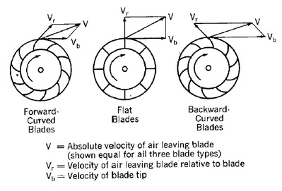
T is the torque required to rotate the blades through the air at the speed (N) required for a free-flowing impeller. The following table summarises the characteristics you can expect from your fan dependent upon the shape of its blades (Fig 3). These extremely technical devices designed to supply higher pressure at a quantitative relation of one1.1 to 1.2.
centrifugal impeller calculations blowers crank portion

0000006897 00000 n
it is advisable to minimise the number of blades in high flow-rate fans.
centrifugal ashrae lec blowers compressors brant centrifugal blowers blower compressor air drawing facts fast power stage specific gas constant (air): R = 283.5383565 {J/K/kg}
Efficiency at these (optimum) angles varies with impeller diameters ( and ) but is unaffected by variations in operating speed (N). 1.05 bar represents unusually high pressure and may be ignored for general applications. Multi-stage fans are normally used to increase outlet pressure, but are comparatively expensive.
velocity impeller pump centrifugal triangle head triangles engineering twist inlet outlet density independent liquid mechanical come formula populer stackexchange theoretical You can include this effect if you wish by using the following formula:
is the efficiency of the fan (which is normally between 50% and 90% dependent upon gas and design). You will find that some changes to input data reduce one loss but raise another so a little trial and error is required to maximise efficiency. v and v: the absolute velocity of the air at the inlet and outlet edges of the blade and will vary from inlet to outlet for both axial and centrifugal fans. each fan in the sequence increases pressure over the previous fan until you have achieved the pressure required. but all of them will shift gases at the same rate based upon the input power. In order to lower
Such a configuration is also difficult to balance. 0000004012 00000 n
For example; an impeller of 0.5m diameter with an ID of 0.1m will never achieve the flow rate for which the impeller OD is capable unless the inlet pressure/flow-rate is artificially increased. hbbd``b`VS`g@,`IR$F6$|2A&30_
@
D
The material handling business uses gas pressure systems to manoeuvre granular and powder materials to production. air density at impeller inlet: = 1.2 {kg/m}
RAM is the relative atomic mass of the gas (e.g. For general applications, maximum isentropic efficiency will be achieved by selecting small inlet angles and large outlet angles, however, this will be at the expense of head efficiency. %PDF-1.5
%
centrifugal blower animation fan fans inline radial rebel duct quiet powerful 0000000016 00000 n
If you just alter the outlet angle without adjusting the inlet angle you will struggle to find a solution. <]>>
Whilst it can be difficult to recalculate a manufacturer's working fan if most of the input data is unknown, it can be reproduced by playing with the blade tip angles ( & ). This does not mean Innes' theory doesn't work, it means that the air will not flow over the fan correctly. 0000006629 00000 n
Fans calculates the airflow through an impeller together with the expected effects a restricted casing diffuser would generate. A simple calculation procedure you may use to establish the output flow rate of the fan (impeller inside a casing) is provided in the calculators technical help menu. The ninety-nine potency of the system guarantees that each one of harmful odours, contaminants, and gas fumes are removed. 520 0 obj<>stream
It is therefore necessary to play with these to achieve the desired results.
1) List your operating parameters (flow-rate, head, pressure-rise, etc.). This value is equal to 'v' in axial fans, v is the velocity of the air passing over the blades at the inlet edge of the blades, v is the velocity of the air passing over the blades at the outlet edge of the blades, v is the rotational velocity component of the air at the inlet edge of the blades (this value is zero for axial fans), v is the rotational velocity component of the air at the outlet edge of the blades, A is the airflow area through the blades of an axial impeller, Ar is the ratio of inlet and outlet areas (Ai:Ao), Ai is the airflow inlet area through the blades of a centrifugal impeller, Ao is the airflow outlet area through the blades of a centrifugal impeller. For a few industries, dirt assortment is necessary a part of their operations, also as being legal. This should also include the velocity pressure on the outlet side (if known) that is constant and in line with the fan as well as the velocity pressure (p) generated by the fan. p = p .v. {use '+' if the direction of movement is towards the fan and '-' if it is moving away from the fan}, Velocity Pressure; is the pressure generated by the gas moving through the fan, Discharge Pressure; is the sum of the velocity pressure and the difference between the outlet pressure and the inlet pressure (Fig 2), Static Pressure; is the maximum of the inlet and outlet pressures, Pressure Head; is the head generated by the discharge pressure at the outlet side of the fan, The shape of your blades and the direction they travel will define the performance characteristics of your fan. This value must be set to 1 (one) if p is in units of mass per unit area such as kgf/m or lbf/ft. These values have therefore been estimated for the Fans calculation. This value is zero for axial fans. If this angle is less than '' a warning will appear to increase its value, is the length of the blades between the inlet and outlet edges in an axial fan, w is the width of the blades in a centrifugal fan, parallel to the axis of rotation of the impeller, is the density of the air at the inlet edge of the fan blades, p is the pressure of the air at the inlet edge of the fan blades, T is the temperature of the air at the inlet edge of the fan blades, R is the specific (or mass) gas constant, F is the coefficient of friction of air (with the blades). impeller). CalQlata recommends that final design calculations should be made on the basis of specifications and procedures recommended by your selected supplier. 2 Blades: Significantly improved airflow characteristics than one blade designs but still generates significant turbulence (behind each blade). Even forward facing blades should have inlet angles <90 {'forward facing' refers to the outlet angle only}, is the angle of the outlet tip of the blade which can only be between 0 and 180. The secret here is to ensure that inlet angle is very shallow (e.g. the difference between the inlet and outlet pressures plus the velocity pressure, ps is the static pressure in the fan; i.e.
0000092243 00000 n
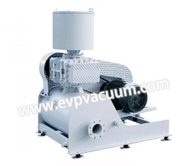
<< 45; i.e. An industrial blower could be a device that enhances the air flow in an exceedingly effectively and expeditiously by using an electrical motor, impeller, and air foils.
centrifugal sciencedirect 0000085441 00000 n
impeller width: w = 0.0616 {m}
For the purposes of this description; the outlet area of a diffuser is the orifice furthest from the impeller. 0000001097 00000 n
xbbb`b``3
1 |
Note: angles greater than 90 will struggle to generate the inlet velocity required to initiate throughput. 4 Blades: Better airflow than the 3-Blade configuration but 33% greater skin friction.
; If you are using metric units, you may find it simpler to use metres and kilograms and for Imperial calculations, you should find it easier to use feet and pounds (avoirdupois) as the gas constant is readily available in these units. 770 0 obj
<>stream
Energy (L): Air leaving the impeller of a centrifugal fan contains stored energy that is not converted into head or velocity. For example:
A comparison between the efficiency and performance of equivalent Axial and Centrifugal impellers is provided below
air pressure at impeller inlet: p = 101325 {Pa}
You need not concern yourself with pressures lower than 1 bar as flow rates under such conditions will be achieved with less power input. If the fan outlet diffuser area is less than the surface area of the impeller outside diameter (), this flow rate will not be achieved by the fan. In order to lower
calculations centrifugal