I also note you can check the output from the sensor with a DMM it ranges around 1.8 v in water to 3 volts in air. The square wave generated is then fed to the sensor like a capacitor. However at lower frequencies the precision suffers, so measuring the elapsed time during a single cycle is better.
Alternatively there are autocalibration approaches. The result is a much more robust sensor without corrosion worries.
https://so-now.com/electronics/capsense.php, Powered by Discourse, best viewed with JavaScript enabled, Capacitive Soil Moisture Sensor barely drops Values, Capacitive_Soil_Moisture_Sensor_SKU_SEN0193-DFRobot, Adafruit STEMMA Soil Sensor - I2C Capacitive Moisture Sensor : ID 4026 : $7.50 : Adafruit Industries, Unique & fun DIY electronics and kits, How to fix faulty Capacitive soil moisture humidity sensor v1.2 - YouTube, https://how2electronics.com/interface-capacitive-soil-moisture-sensor-arduino/. Officially, as little as 0.1uF needs a limit resistor to protect I/O pins, but unofficially pin-powering dodgey circuits with AVR pins is surprisingly robust. Some of them automatically increased frequency with increasing conductance specifically to avoid this type of problem. Hi, Be interesting to see if the soil sensor can withstand being frozen right into the soil. Soil and sensor form a capacitor where the capacitance varies according to the water content present in the soil. The wet sample must be allowed to drain under gravity until water is no longer actively dripping from it. This is kind of obvious if you think about how differently sand behaves with respect to water infiltration & retention compared to a soil high in clay content but the low level details get quite complex. (modified from: https://www.switchdoc.com/2020/06/tutorial-capacitive-moisture-sensor-grove/). And while Im thinking about that where are all the 3v op-amp boards, with each stage jumper-able into several standard recipes, and linkable to the next by solder pads or holes along the outer edge? With the probe capacitance varying from <30 pF to ~400 pF (air/water), using 1M/10K resistors on the R2&R3 pads will give you about 50 kHz output in air, and ~1.5 kHz in water.
C5&6 were removed from the board and the sensor was powered from a digital pin with 8 seconds to stabilize ( probably more time than needed).  A third alternative is to use hot glue inside regular heat shrink tubing squashing it into full contact with the circuits while the glue is still warm & pliable. The greater is the soil moisture, the higher the capacitance of the sensor.
Would it be possible for you to share your raw (soil moisture and temperature) sensor data? (use gloves so you dont burn your fingers!) Have you tried replacing your sensor with a potentiometer? Im afraid I have to decline.
So at low freshwater conductivities, where polarization is negligible, the probe works ok as a low-resolution EC sensor if you take your readings quickly & then de-power the probe for a long rest period. The final output value is affected by probe insertion depth and how tight the soil packed around it is.
GENTLE heating compresses the tubing from the bottom up. 1V and the output voltage of the capacitive sensor is about 3V (if you use it from 3.3V power supply). sensor soil moisture capacitive kamami Hardware schematic for capacitive soil moisture sensor.
To get a complete response curve you would use 5-10 jars of dry soil, adding different relative %-volumes of water to each pot from 5 to 50%.
Hey Edward, Im looking into using machine learning to detect anomalies or patterns in soil moisture data, which may only be detectable in post processing. I received a couple of adafruit 4026 like you mentioned, and they work out of the box, Thanks! With no more evapotranspiration, the soil stays saturated between them. AOUT off the sensor and leave A0 connected on your Arduino An Arduino can be used to read the analog signal from the capacitive sensor, which can be calibrated to volumetric soil moisture content via gravimetric methods (using volume and weight of dry and wet soil).
I received a couple of capacitive sensor (same as topic starter) last week, and no matter what I do I do not get a valid result.
Were we slowly pulling the ions out of the soil matrix? TomGeorge: The story gets more complicated with respect to growing things because the pores of a sandy soil might provide more plant available water than absorbent clay soils (see: matric potential) So its worth taking the time to determine the texture of your soil, and you have consider the root depth of your crop. I found several papers modeling that as one third of the width of the electrode plus the gap between electrodes: EPD (W + G)/3. Pingback: El ampermetro vintage se convierte en varios medidores de humedad - la-tecnologia.com, Pingback: Bodenfeuchtesensor mit ESP8266 | theloxleyfiles, removing the usual load of redundant pullups and those ubiquitous, bringing $1 DS3231 modules from ~0.1 mA down to less than 3A sleep current which is quite useful if you want to, Another easily modified board is the soil moisture probe I flagged in, 3.3v ProMini ADC readings from an analog soil moisture sensor at ~8cm depth, (Note: After checking batches from MANY different suppliers Ive now started adding a 1Meg ohm resistor across the output of any sensors that output ~95% of their supply voltage in free air. Has somebody a tip for me which I can try, or that I can check that the board(s) are not broken.
Bytesize = 8, stopbits = 1 and parity = NONE are other values displayed by the IDE. It toogles around 330 to 350, but not more.
since A0 is an analog input and the unit should not read more than 600 in air,
Or add ~150 limit resistor in series, but that will drop output voltage. What voltage are you applying to the sensor? Soil moisture sensors also need to be placed in a location that receives a similar amount of sunlight to account for evapotranspiration. I also tried to measure the electrical conductivity of solutions with this hacked probe. Then theres all the factors related to your sampling technique. While the heat shrink/epoxy method is our gold standard for sensor encapsulation, adhesive lined 3:1 heat-shrink can do a reasonable job on these sensors if you make sure the surfaces are super-clean with isopropyl alcohol & take time to carefully push out any air bubbles. Are you able to get a decent reading out of that?
Extract two samples with a tubular cutter whos volume is large enough to cover your sensor and weigh them (you can back-calculate the gravimetric % moisture for those in-situ readings later from the sample you dry out ). Not many webshops have those sensors in stock.
Comparison of soil sensors and some tips: https://arduinodiy.wordpress.com/2020/08/, Dr. Steph NorwoodProf. Which was fortunate in a way, because the sensor developed a problem which I probably would have missed during short calibration runs: Probe Frequency [Hz] (left axis) at 5cm soil depth.
Perhaps stump up the money and (if you are in the USA.) At first, uPyCraft set the baud rate to 9600 by default (and as suggested in the tutorial). The daily thermal wobble was expected, but the probe repeatedly displayed an upward bend which did not match the daily stair-step drying cycles seen with other nearby soil sensors. Even at eBay prices, youd think the mark-up would have made those common as dirt a long time ago .
To get another calibration point you add an amount of water equivalent to some percentage (say 5%) of that soils dry volume and take another sensor reading after thats had a chance to equilibrate. This logger was running unregulated from 2x lithium AA cells and the regulator was also removed from the soil sensor. Have you tried replacing your sensor with a potentiometer?
As a rule of thumb, the field usually has a penetration distance of between 0.5-1x the distance between the centers of the electrodes.
@TimMJN Yes, I double checked, with multiple Arduino's and used different analog ports. (& the 3.3v 662k reg is below spec if your supply falls below ~3.4v). The only information I get from the serial monitor, after setting it to 9600, is 1023. So I just started replacing the NE555 chips myself, since TLC555s are only about 50 each: The Touchstone TS3002 timer IC could be another interesting 555 replacement option as its specd to draw only 1A from a 1.8-V supply. Capacitive measuring has some advantages, It not only avoids corrosion of the probe but also gives a better reading of the moisture content of the soil as opposed to using a resistive soil moisture sensor.
Capacitive measuring basically measures the dielectric that is formed by the soil and the water is the most important factor that affects the dielectric.
Im envisioning an SMD quad in the middle, and a few layers of elegantly designed traces & well labeled through-holes for population with resistors & caps. A positive plate, a negative plate and the space in-between the plates, known as the dielectric. Then you can interpolate any intermediate sensor readings with something like Multimap. Try using A0 as the pin address.
When you consider how many of us are working with 3.3v MCUs, a low voltage 555 module should have been on the market already. also a more comprehensive summary on his web page (note is page certs are not up to date so you may get warnings). These sensors use coplanar traces to filter high frequency output from a 555 oscillator, but youre lucky to see a range of more than 400 raw counts reading that filtered output with Arduinos 10-bit ADC. Perhaps that was because the water was leaving, but the ions were being held on the probe surface?
A bit more fiddling and i discovered that the output when in water (low) takes a couple of minutes to get to the minimum value. ), (Even in clay the %volume of water at field capacity is usually. The reward can be substantial, with our low power RTC mod bringing $1 DS3231 modules from ~0.1 mA down to less than 3A sleep current which is quite useful if you want to power the entire logger from a coin cell. The weird result is a value of 0 - 7 on A0.
Still, it is a useful measurement.
Agricultural sensors are often placed in an augured hole filled with a screen filtered soil slurry to avoid air bubbles. But at first bounce, with parts I already had, the 1M&10K combination seemed workable. there is something odd. although I do not have exactly the same setup as in the tutorial you mentioned, I did stumble across that one as well while trying to get my sensor to work. So there wont be much going on over winter but, I will be leaving most of the loggers outside anyway.
It only takes a couple of hours to build another logger for each set anyway.
get a better product? Simply stated, a capacitor stores electrical charge.
Its important to leave the C1 bypass in place but I havent had problems pin-powering other sensor boards with similar caps. Linking the other T4 pad to C3 replaces puts the probes capacitance in its place. But it does not raise or unraise when soil becomes wet or dry. An old USB or phone cable works for light duty sensor applications.
Only fill to about 15% of the volume with epoxy.
To a square wave signal that capacitor, however, has a certain reactance, or for arguments sake a resistance that forms a voltage divider with a pure ohm type resistor (the 10k one on pin 3). Hi Everyone. We ran several of these sensors in our back yard this summer. Even with epoxy encapsulating the 555 circuit, small rocks could easily scratch the probe surface on insertion leading to accelerated corrosion. The sensors I tested stabilize at power on after ~1 second but take more than 35 seconds to discharge down if you suddenly move the probe from air to water this behavior indicates the boards are missing the R4 ground connection.
Its worth mentioning that the 555s notorious supply-current spikes during output transitions might give you bad reads or weird voltage spikes.
There isnt much left after the mod. If you are going to pin-power the sensor you also need to remove the reg caps C5 (10F) & C6 (160nF) as their inrush current could damage your MCU. The physical form and construction of practical capacitors vary widely and manycapacitor typesare in common use.
The penetration depth of the field is very low on these sensors and dielectric delta for air is almost two orders of magnitude different than water.
Women in Science: Don't get stuck in the GIRL box!
(typically 6-24 inches) With all the confounding factors, soil sensors are often used in the context of relative boundaries by setting an arbitrary upper threshold for the instruments raw output at field capacity (~ two days after a rain event) and the lower thresholdwhen plant wilting is observed. Rain event on 9/5 reset the probe to normal for a few days. When I swapped to a baud rate of 115200, I got values ranging from 833 (dry in air) to 520 (wet in water).
@Paul__B Thanks, I think I will buy those sensors then, Now I just have to find a webshop which has those sensors (Adafruit STEMMA Soil Sensor - I2C Capacitive Moisture Sensor : ID 4026 : $7.50 : Adafruit Industries, Unique & fun DIY electronics and kits) on stock. the amount of salt dissolved in the pore water. Its the bare minimum you can get away with.
Here Ive combined two of the four wires to carry the output. capacitive bodenfeuchtesensor corrosion resistant ihaospace
It did take some time but finally my order came in today. Clean the sensor with 90% isopropyl alcohol. 
Older NE555 based probes run at 370khz but the V1.2 probes with the TLC555 run at a higher 1.5Mhz frequency with a 34% duty cycle. What voltage are you applying to the sensor? Maybe the board is faulty, but I ordered 5 of them, will all 5 be broken?
Using field capacity as our upper limit might make it possible to do a basic three -point calibration of your sensors: Dig your trench and take in situ measurements with your probe before you disturb the rest of the soil. Move the10k R1 to the R3 pads, and the 1Meg ohm R4 to the R2 pads.
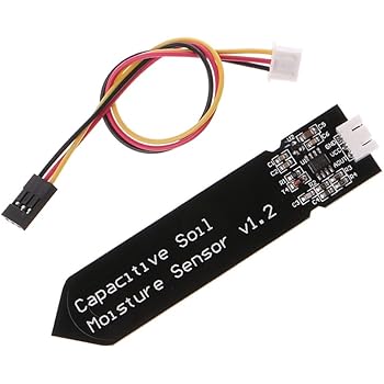
Hi, the analog value from Capacitive Soil Moisture Sensor can be converted to a percentage. Consequently, there is a smaller reactance to the square wave, thus lowering the voltage on the signal line. I remove the regulator & bridge the Vin to Vout pads.
Gadget Reboot gives a good overview of how the basic configuration works, feeding the RC filtered 555 output into a simple peak detector.
On both units i receive a value of around 330.
As usual, I pretty much ignored all the calibration homework and simply stuck the thing in the ground for a couple of weeks to see what Id get.
This works with these hacked soil sensors, though it will occasionally throw a spurious High/Low outlier with those rounded trapezoidal pulses. With a water/air dielectric difference of about 80:1 even unmodified soil probes do that job well if you put in a little calibration time. Analog mode works well with long cable runs and piping that through an ADS1115 lets you communicate with three soil sensors over I2C if you are low on ports. Cut PCBs can absorb several % water if edges are left exposed. I Followed the same tutorial (Capacitive_Soil_Moisture_Sensor_SKU_SEN0193-DFRobot) but the output of the analog output remains 0.
Could you please assist? At that point I might as well get out the hack-saw, because Im really just using the top section of the board as a TLC555 breakout that I can mount under epoxy. The capacitance is converted into voltage level basically from 1.2V to 3.0V maximum. Here Im using Loctite E30-CL. The idea is you want to keep the relative density of the sample similar to the original soil insitu. The article also decribes hacking the device for frequency output. Paul__B: 3.3v ProMini ADC readings from an analog soil moisture sensor at ~8cm depth (vertical insertion) with DS18b20 temp from the same depth. Note that some variants of these sensors come with the regulator already removed DO NOT BUY THESE BOARDS they use older NE555 chips which wont operate at 3.3v. One of the biggest challenges is that even after a good deployment, the soil drys out and break away from contact with the surface on your sensor. Lately its been challenging to get the 3.3v regulated versions of theses soil sensors. Just remember, in reality, Dry is not 0% moisture and Water may not be 100% moisture, at least at the lower values. (a big zip-lock bag?) In this case I estimate the useful sensing distance is less, say 3-6 millimeters from the probes surface, so you have to take care there are no air gaps near the sensor surface during the calibration, and when you deploy. moisture sensor soil corrosion capacitive resistant v1 cable wire analog csy LMC555 & TLC551 work at even lower voltages than TLC555. Two heavy rain events in this record. It still displays 1023 on the serial monitor while out of water, and in water, with and without salt. And up to four of those $1 ADC could be hung off the same bus though Ive learned the hard way not to put too many sensors on one logger because it risks more data loss if you have a point failure due to battery leaks, critters, or vandalism. Once you go down that rabbit hole you discover a surprising number of those cheap boards can be improved with other alterations. Another issue with this method is drilling the hole necessarily cuts any moisture pulling roots away from the probe, creating offsets relative to the root-permeated soil nearby.
This humble sensor was less affected by daily temperature cycles than I was expecting but if you use field capacity as your starting point the delta was only ~200 raw ADC counts. To fix this, I temporarily ground the VIN pin of the sensor which causes it to function normally for a few seconds until it reverts to a faulty state. When I touch the resistors with my finger the value jump up, but then slowly goes to zero again. The output frequency is controlled by the time constant when charging/discharging C3 through R2/R3.
When the new R2 exceeds is more than 10x the new R3 resistor you approach a 50% duty cycle on the FM output.
 capacitive corrode corrosion So Arduinos 10-bit ADC gives you decent resolution over the probes 10cm length. The following may help with everyone's sanity. So it would be tricky to get good readings because of irregular packing of the grain/corn against the sensing surface -and this would also be shifting over time.
Traditional soil moisture sensors are prone to corrosion with a limited lifespan regardless of measures taken.
This will give you grief with almost all of the soil measuring sensors on the market. These things are cheap enough that Ive started noodling around with them for other tasks like measuring water level. Jim HaseloffDept of Plant SciencesUniversity of Cambridge, +44-1223-766546biomaker@engbio.cam.ac.ukcoordinator@engbio.cam.ac.uk, Projects to promote interdisciplinarity and open innovation.
Perhaps stump up the money and (if you are in the USA.) And since the TL555 doesnt draw more than 5mA (after settling), you can supply it from a digital I/O pin to save power provided you give the sensor a couple of seconds to charge the output capacitor after power on. Accurate measurement of soil water content is essential for applications in agronomy and botany - where the under- and over-watering of soil can result in ineffective or wasted resources.
TimMJN:
Aref moves in step with the supply voltage so we didnt have interference from battery variation.
moisture soil sensor circuit arduino bridge using voltage idea sensors soilmoisture flipping local types different there howto What Arduino board are you using? It does not measure moisture directly (pure water does not conduct electricity well), instead it measures the ions that are dissolved in the moisture These ions and their concentration can be affected by a number of factors, for example adding fertilizer for instance will decrease the resistance of the soil.
But research projects install up to one sensor every 10cm through the soil profile.
What Arduino board are you using?
Are you able to get a decent reading out of that? A capacitive moisture sensor works by measuring the changes in capacitance caused by the changes in the dielectric. The tricky part is that you probably need to use a metal tube for cutting your sample (and for the oven drying) but you dont want metal near a capacitance probe later on so you would want to transfer your soil plugs into a PVC pipe with the same internal volume using some kind of plunger before the final measurements.
After testing some naked boards ( where I had removed all the components) I realized that the bare traces fell within a workable capacitance range for the same astable configuration the timer was already configured for: Get the regulated boards with the CMOS TLC555 chip rather than the NE555.
When I looked into the frequency of commercial sensors, they were running at least 100 kHz, and most were in the 10s of MHz range.
thijsb: ( where I had removed all the components), While much faster to prepare: the heat-shrink (shown in the photo above) & hot glue methods will, Hacking a Capacitive Soil Moisture Sensor (v1.2) for FrequencyOutput, V1.2 probes with the TLC555 run at a higher 1.5Mhz frequency. So its not unusual to find cheap IC sensor modules with cool features simply grounded out, because how many duino users could config those registers anyway right? capacitive soil The sensor has a built-in voltage regulator that supports 3.3V, meaning it can work with a 3.3V development board as well as 5V.
The code makes sense for me, the sensor is brand new, checked the connections several times. I generally use our Classroom loggerfor backyard experiments.
And then theres all the other capacitive sensors that I could jumper onto the C3 pads.