 NEMA 17 torque-speed is changeable by applying the different operating speeds.
  Inside the loop() function we will first rotate the stepper motor in clockwise direction at a faster speed and then rotate it in the opposite direction at a slower speed. higher than 8V. document.getElementById( "ak_js_1" ).setAttribute( "value", ( new Date() ).getTime() ); Our philosophy is simple. stepper a4988 impresora Your 2.8A motors would run with this current, but not at their rated strength/speed.
Connect the first coil to 1A and 1B and the second coil to 2A and 2B. For us, thats using electronics to make ideas a reality! The key features are: The number of steps that this stepper motor has in a full step is 16 steps. arduino a4988 stepper potentiometer control schrittmotor schaltplan ansteuern lab This will protect the IC in case the temperature exceeds a higher value. The A4988 stepper motor driver is intended to drive a bipolar stepper motor. 
Also microstepping seems to help the motor run quieter/cooler (but I don't know why). VMOT, GND: This is the stepper motor power supply pins. arduino motor stepper a4988 driver control Focus on one thing and be the best at it. on Introduction. With thelarge heat sink to ensure good heat dissipation. A high signal will disable the outputs. printer 3d arduino drv8825 a4988 stepper driver motor control module Next is loading an Arduino sketch and Setting the Current limit on the StepStick, Here is the initial sketch I loaded to my Arduino. Also the higher the voltage the faster/ more accurate the step and generally I found it a good idea to use the highest possible voltage and correspondingly decrease the current to avoid burning out the motor. 1A: This is connected with motor coil 1 first pin. However, you can use any other suitable Arduino digital pins as well. By changing these 3 pins, you can change the step from full step to step 1/16. This is an interesting article. PS would it not make sense to have your primary image showing what you are using rather than an apparently random pick of one of the many combos of motor/driver you aren't using? Make sure the GND pins are connected with the respective common grounds. 5 years ago. The converter is the key to the easy implementation of the A4988. This will be the same in value as before but with a negative sign.
Your email address will not be published. upset with this, Ravi Teja This is set via the adjustable resistor on the board, in co-operation with some of the other components, the sense resistors (S1 and S2) and the resistor (R1). Thus it should have been entirely possible to use your adafruit driver with your stated specs.
There are no phase sequence tables, the high-frequency control interface programming etc. Add to cart to save with this special offer. So, I got some stepsticks and decided to wire them up to my Arduino. It is the drivers you're using that are weak. Additionally, we can also add a capacitor(minimum 47uF) with the external power supply connected with the stepper motor power supply pins to avoid voltage spike issues. Your Rating
// The next steps are similar to the previous one. The moveTo() method takes in the argument steps per revolution which are 200 as we are using NEMA 17. We have used digital pin 6 to connect with DIR and digital pin 7 to connect with STEP.
Using only two pins of Arduino and A4988 driver module, we can control the speed of the rotation as well as the direction of rotation of a stepper motor. Would someone be able to tell my why it fried? However, with cooling feature the maximum allowed current per phase will be 2A instead.
a4988 thermique stepper pololu The low power dissipation of synchronous rectifier. I start with the trim pot turned anti-clockwise, and measure the voltage with my multimeter between the logic Gnd pin and the centre of the trimpot itself, slowly turning it up until I get just under 1.12V.
Fully NMOS H-Bridge for better efficiency and no heat sink is required. Connect the output pins of the driver with the respective motor pins. I posted the question here. I connected this to Pin 6 on the Arduino, Sleep and Reset control the board, either sending it to sleep or resetting it. This warranty is given for the benefit of Robu customers from any kind of manufacturing defects. Total inductance by each phase will be 2.8 mH. I was wondering if you could help me modify this code in order for it to work with a A4988 driver , its a frameless laser harp , cant wait to finish it ! motor a4988 driver stepper arduino pinout pins module schematic adjust interface familiarize ourselves let 1.0A(No Heatsink ), 2.0A (with Heat-Sinking). Did you make this project? I've attached a pic of my A4988 in case that helps. There is a built in translator which allows only two pins from the Arduino board to be used to control the speed and direction of the stepper motor.
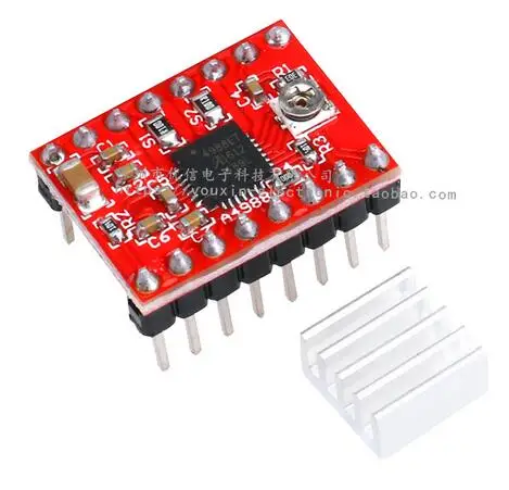
I've read elsewhere that steppers cannot execute steps simultaneously and they must step one at a time. SLP: This is also an active low input pin which is used to reduce power consumption by setting the module to sleep mode when the motors are not in use. Save my name, email, and website in this browser for the next time I comment. It sets the internal translator to a predefined Home state which is the position where the motor starts initially. Once you have this working, theres several things you can do to expand. Support motor voltage ranges from 7V to 25V, . We will show you how to rotate the motor in both directions. It allows the IC to cool down if temperatures go higher than safe ones. We can easily attach the heatsink on top of the A4988 IC as shown in the diagram above. In the stepping operation, the chopping control in the A4988 automatically selects the current decay mode (slow or mixed). The mix decay current control scheme can reduce the audible motor noise, increased step accuracy, and reduced power consumption. First, we define pins 5 and 6 as STEP and DIR pins. 2. Connect 8-35V external power supply with VMOT and common ground. Then the loop will start again. Bi-directional control of 1 brushed DC motor. The figure below shows the 16 pins that are present on the A4988 Driver Module: The module has a total of 16 pins which can be divided in four categories: the output pins in blue which will be connected with the motor, the control pins in green, the step size selection pins in brown and the power pins in red. This code will help us control the stepper motor using the A9488 drivers DIR and STEP pins. Prepare one yourself. Next, go to Tools > Port and select the appropriate port through which your board is connected. The stepper motor will start rotating clockwise and then anti-clockwise repeatedly. DIY, Wireless, Modular, Arduino, 3D Printed!
2 Amp 1.4 Ohms per coil are actually really good stepper motors. DIR: This is the pin which controls the direction of the rotation of the motor. The Adafruit stepper motor shield cant supply 2A,and has trouble with voltages below about 5V, so couldn't properly run my motors (they jittered but didn't smoothly move). NOTE: I did not have reset wired to sleep, however. Dont need special power-up sequencing. For my stepsticks S1 and S2 are marked 'R10' and R1 is marked '303' (in very small writing !).
Internally to control the stepper motor we will have to use the green and black pair. Automatic current decay mode detection / choice. Your email address will not be published. 6 years ago Reimbursement or replacement will be done against manufacturing defects. The following circuit show how you should connect Arduino to A4988 module. stepper a4988 The A4988 Driver Module is used to control the speed and direction of stepper motors mainly used in robotics, toys, 3D printers for motion control. Additionally, the serial monitor will display the direction of the motion of the motor. a4988 driver motor stepper heatsink pololu ramps reprap arduino module 3d 5pcs So it is always advisable to use the heatsink. Rate Item as described, prompt shipping, great pricing, thank you: A+. It is used to turn the outputs of the module on or off. To prevent damage to the driver chip, it uses circuitry to limit the maximum current that can be used. This item is covered with a standard warranty of 15 days from the time of delivery against manufacturing defects only.
We are using 12V external power supply. There are no answers for this question yet. These correspond to 0.1Ohm for S1 and S2 and 30kOhm for R1. As you can see we have used digital pins 6 and 7 to connect with DIR and STEP respectively.
We will use the pinMode() function to configure the digital pins connected with STEP and DIR as output pins. This instructable covers the third method, running one or more steppers via an A4988 IC on a StepStick board.
Some hookup wire, I used solid Cat5 strands. However, it cannot be said that this relationship is always true. In this getting started tutorial, we will learn to interface the A4988 stepper motor driver module with Arduino. Is the dir & step is same thing as dir & pull in TB6600 driver? Click on the upload button to upload the code into the board.After you have uploaded your code to the development board, press its RST button. Connect 3-5.5V from a microcontroller with VCC and common ground with a microcontroller. Unlike other DC motors, they provide a precise position control according to the number of steps per revolution for which the motor is designed.
Internal circuit protection includes thermal shutdown with hysteresis, under-voltage lockout (UVLO) and crossover current protection. That means a complete revolution of a stepper motor is divided into a discrete number of steps. By increasing/decreasing the delay we are basically changing the frequency of the signal which then alters the speed of the motor. Reply Reply Type Accelstepper in the search bar and install the latest version. The speed of the motor rotation will change according to how soon the signal of the pin goes high. How to stop the stepper .. 4 years ago You say "The trimpot should be 10kOhm", but I don't understand how you determined that. The next step is to define the digital pins of Arduino we have connected with the DIR and STEP pins of the driver. They rotate in discrete steps of predefined values and are able to rotate both clockwise and anticlockwise. An Arduino Uno, but any Arduino compatible should do, A Stepstick, or compatible stepper driver using a A4988 or DRV8825.
Open your Arduino IDE and go to Sketch > Include Libraries > Manage Libraries.