Just a PNG not a full functionnal fritzing part. Hello, Im sorry, Im not familiar with the ESPHome, I think you could use the Adafruit SSD1306 library: I have just replaced the miliseconds check with a delay(1000). inputStatsS.setWindowSecs( windowLength ); RunningStatistics inputStatsT; //Easy life lines, actual calculation of the RMS requires a load of coding I need to add that when I exceed 15 VAC, I will trigger an output of 5 V on the arduino. So the project today is how to measure AC voltage up to 250V, in both 50Hz and 60Hz, using the ZMPT101B, thats the name of the transformer only, but youll find it around with this name or AC voltage sensor. Also dont forget that the module delivers a sinewave signal not a continuous one, if you just use the serial monitor to see the values it will show strange different values, and it would be difficult to measure them when AC is on. Check:Measure any AC voltage (250VAC) with ZMPT101B and ESP8266 12E with Android App / Adafruit IO MQTT. First, you should use code 1 to get the maximum of the output voltage of the sensor.
So adapted Gerhards version in the following way. Hi. Nevermind, I hit the problem. current_VoltsR = current_VoltsR*(40.3231); //Further calibrations for the amplitude Hi, sorry I didnt tried it with an ESP32, but first the module should be powred by 5v, you should use an external source as the operating voltage of the ESP is around 3.3v I think, use the VCC and GND for power, then for the ESP32 use an Analog input and GND with the Signal and GND from the module, and make sure to use a proper level shifter, I think a voltage divider can do the work. To use this library, open the Library Manager in It needs to be installed, search on how to do it. Note: I also got the same values when I tried to separate them like that Here you can see, to measure the RMS you shouldnt only measure the peaks and do the same calculations for the Sinewave signal. I have doubts about Arduino program. If nothing is connected to the module inputs (module input is 0 volts), your diagram will show a number around 512 (i.e. thank you for your conitnous support, I have applied 220v AC , but there is no change in value of Serial.println(analogRead(15)). 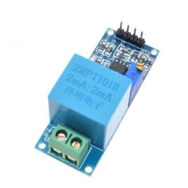 i do not see people working on ESP32 much on internet inputStats.setWindowSecs( windowLength ); Suggest corrections and new documentation via GitHub. }. As salam alaikm dear Our philosophy is simple. It is already answered in the previous comments. In order to calculate the input AC Voltage, you need to find the maximum of the output -Vmax_v- and use the formula given in the second code -step 3 section-. inputStatsR.input(SensorR); // log to Stats function Make sure the sine wave is complete in the serial plotter, specifically the minimum and maximum parts of the chart. Hi. which can be 2.5, 6 or 11 dB. Library to interact with the ZMPT101B Voltage sensor. how to draw zpt101b with fritzing ? // put your main code here, to run repeatedly: //Determine the incoming AC voltage on each phase Suggest corrections and new documentation via GitHub. Hi, Serial.println(fBluePhaseVoltage); but there is no change in this value even I connect or disconnect AC power. So, I give you the same answer. Hello, nice tutorial I tried your code and its Woking very well. Hi, inputStatsT.input(SensorT); // log to Stats function, if((unsigned long)(millis() - previousMillis) >= printPeriod) { And about ESP32, you need to replace 511 with 2050. And for example here I used a light dimmer, which is based on a Triac and you know the weird shape of the signal that a Triac makes. Im try to implement 3 phase voltage meter using esp32.. current_VoltsS = current_VoltsS*(40.3231); //Further calibrations for the amplitude You need 2 other variables for all: Doubts on how to use Github? AC_Voltage_Measuring:53:3: error: inputStats was not declared in this scope when I pull out cable from shifter-To-ESP32(pin15), there is zero value on it. ==> if this works it means your module is working well, 2) Try this but this time use (3.3V/GND), no AC voltage -> measure -> it should be half 3.3 which is 1.65V. lcd.begin(16, 2); void loop() { This is the whole wiring, and as mentionned Im using an 12832 OLED screen you can use it or no, the module is powred by 5v and delivers an analog signal. You can see that the maximum voltage is somewhere around 600. Do you have any work around for this issue?
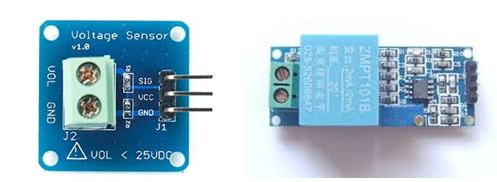
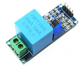
I add a delay because im sending the measurement into a web database. RunningStatistics inputStats; //Easy life lines, actual calculation of the RMS requires a load of coding I found this GitHub: Thats all folks, I hope you like it, be careful and if you have any probel feel free to contact me, dont forget to support the channel by a subscribe. float fBluePhaseVoltage; // stores the voltage in the Blue Phase. I am someone from the old school VB background and am not too familar with the C syntax, also this is very first Arduino project, which I am doing it for my in-house purpose. You can measure AC voltages up to 250 volts by using this module. Required fields are marked *. { or maybe you would recommend some other way to do it instead? 1) Power the ZMPT101B with (5V/GND), do not add AC voltage, measure the (Signal/Gnd) pins with a multimeter (DC Voltage), the voltage should be around 2.5V, because 2.5V is the offset. if(condition) const int iBluePhaseSensorPin = 2; //Sensor analog input, pin A2 Thank you for reply, Please advise further for module working as I am fear that module is faulty. https://drive.google.com/drive/u/0/folders/1QWjyMn-uxsei6WB1oH7e40QBTEZVho1_. 3 of these part: Need this with ESP8266 12E (NodeMcu)? const float fSlope = 0.0405; // to be adjusted based on calibration testing Im doing exact the same thing and trying to make ZMPT101B work with ESP32. may i beg your zmpt101b fritzing parts? Do you have any suggestion? 2.5 volts). Sensor=2; for 3 inputs. I want to check all 3 line with 3 ZMPT101Bs. Hi, after the functions that display the readings you can add what you want in a if statement https://www.arduino.cc/reference/en/language/structure/control-structure/if/ voltage ac using arduino sensor divider transformer develop discuss technique figure First, the peak value of the sensor output voltage is divided by sqrt(2). const float fIntercept = -0.04; // to be adjusted based on calibration testing I tired to separate them to get be able to do other stuff but I didnt succed for the moment I will try to do it again, because the goal of this tutorial is just measuring. Nassau, Bahamas is having terrible power issues this summer, where BPL shuts off parts of the city for 3-4 hours, rotating limited power to homes. -Since it is needed for calculating the RMS- Then the rest is just a linear transformation to get an output around 220 from the sensor output voltage. int SensorT = 2; //Sensor analog input, here it's A0, float intercept = -0.04; // to be adjusted based on calibration testing I have adjusted the Trim Pot as you suggested ..and the readings look good . Hello. Ill just copy it here: This module measures the peak-to-peak voltage. Another video will be up soon that uses the same method to calculate the alternating current. After that i supply with known voltage and adjust Slope while I reach the known voltage. Yes, you actually need to rewrite most of the formulas. The potentiometer on this module is multi-turn. Learn everything you need to know in this tutorial. Thank you. So, Im afraid its not suitable for your application. Hi, did you ask me on hackster? inputStats.input(iSensor); //log to Stats function Hi, voltage is almost 2.6v to 3.3 v on pin15. hi, Im about to do the project that using ZMPT101b,, but, first of all I need to draw the sketch in fritzing apps. I was looking for the ZMPT101b parts library in (.fzpz) format on internet, but havent find any result. if you change input voltage, the output voltage will change as well.
current_Volts= current_Volts*(40.3231); //Further calibrations for the amplitude.
Thank you! Hi. btw i need zmpt101b fritzing part and i have search but i didnt find the part. Im combining the ACS712 and the ZMPT101B in one code at the same time. i suspect is because i do other work in the main arduino loop besides calling this functions. ESP-12 (and ESP8266) has the watchdog(WDT) turned on by default. I wont to ask you for using zmpt101b for mesuring up to 400v. First, Thx for this very informative post! Could you tell me what I should add in the code? and dont forget to declare the pin and its mode. Actually, no, it can only measure AC voltage. You can see the result in the Serial Monitor. Thanks Yassine. As you can see in the article, this module is designed to measure high voltages up to 250V. Hi, https://electropeak.com/learn/interfacing-acs712-current-module-with-arduino/ because I had the same question toda, and I responded there. Questions: 1- Im using an ESP32 microcontroller with Home Assistant (ESPHome). hello, has anyone tried this on 60Hz frequency to measure 220-240V? Can you direct me to a place where I can get GOOD TESTED modules?
Since there is while (true) in the code, loop is getting stuck here and current, power, energy etc measurement is not happening. thank you for being willing to help. Veff = (((VeffD 420.76) / -90.24) * -210.2) + 210.2; Hello. It would be highly appreciate, if you can give me a hand.. current sensor ac meter electricity arduino 5a module m4 transformer itead ta12 standard lcd.setCursor(5,1); And here pay attention, some codes around are used with this module, they only do a sampling of the signal and measure the peaks then a little multiplication,and it can show you the RMS of this signal, but those codes work only for perfect sinewave signal, if youre measuring another shape of the signal it would be false. unsigned long previousMillis = 0; void setup() { float slope = 1.26; // to be adjusted based on calibration testing Hi.
Hi sir can you help me how can I combine acs712 and zmpt101b in one code with filters library to measuring voltage and current in the same time.
Interfacing DHT11 Temperature/Humidity Sensor with Arduino, Interfacing ACS712 Current Module with Arduino. float intercept = -0.04; // to be adjusted based on calibration testing float current_VoltsR; // Voltage boards. 2. at 3.3v, this time use (3.3V/GND), no AC voltage -> measured reading 1.65v I cannot adjust the potentiometer, even after 1 hora spinning for both directions. Serial.print(fYellowPhaseVoltage); As you can see in the first section of the tutorial, the ZMP101b module can only measure AC voltages up to 250 volts. For the intercept and slope, you should modify them depending on your calibration, first dont forget to set the module potentiometer as I showed in the tutorial, just by observing the serial plotter until you get an acceptable shape. current_VoltsT = intercept + slope * inputStatsT.sigma(); //Calibartions for offset and amplitude It worked, but when i add a delay the measurement become off, do you know why? 3) If the (2) doesnt work and (1) works well, try to use the level shifter, and make sure its working well, wire everything and check some test codes. The value for out put is sth between 0-5 V. in this situation if I connect the module to 120V and 230V, what we will be the value of output? The only thing I can mention, is to pay attention to the values, I operate the module with 5V, ESP32 has 3.3V, so try to adapt the values. About the multimeter, cheap multimeters measure all AC signals as sinewaves, if you want to use it to calibrate, measure AC sinewave signal from a socket or after a transformer, but since I used a Triac based light dimmer I had to use a TRMS multimeter to get the right value., You can start by the values given above, as I said they are very sensitive, or you can put the Analog input to 0 and make slop=0 then adjust the intercept to get 0 as the result, then put the voltage to a known value, and the intercept to its new value and adjust the slope. When you have something like this you can add a delay to see a nice sinewave, here its because Im measuring right after my light dimmer youll see a little peak before the signal peak if you measure the socket directly you wont have this. If I understood you correctly, First I set the Slope=0, put no voltage to the module, and adjust intercept, so the value given in the serial monitor to be 0. RunningStatistics inputStatsR; //Easy life lines, actual calculation of the RMS requires a load of coding Did you remove that while(true)? fVoltage = fIntercept + fSlope * inputStats.sigma(); //Calibartions for offset and amplitude It helped us enormously in our project. Find anything that can be improved? arduino voltage ac current sensors You can directly connect that wire to any of the analog pins of your Arduino board and use the analogRead() function to measure the voltage. Add now an AC voltage and check the shape of the signal, turn the potentiometer unitl you have a shape like I found, you can add a delay after the serial print if you want. Hello Surtrtech,
PLease help in it, Hi, I dont know what you mean by perimeters, is it something in the code or materials?? When BPL switches power back on, many homes get immediately hit with power surges that burn out electrics, fridges, radios, TV, etc. 3 different currents volts, How did you calculate the calibration values? Youre seeing this ad based on the products relevance to your search query. In this code, first it finds the maximum measured value (peak voltage) and then converts it to RMS value. i was stuck in it. First, the peak value of the sensor output voltage is divided by sqrt(2). Unfortunately I don't use Arduino IDE, I use ESP-IDF, so as for Arduino code, I can't tell you anything. How do I use the Sigma function for both? And you can see that the output is actually an AC voltage. How would you derive a formula please and thank you. fBluePhaseVoltage = GetACVoltage(iBluePhaseSensorPin); Serial.print(Voltages R:); float slope = 0.0405; // to be adjusted based on calibration testing And heres how its derived: The graph of the sensor output voltage when it has the city electricity as its input is given as the result of the first code. Would you have any tip to help me? 2-Any Suggestions about incorporating the 2 libraries into Home assistant (Adafruit SSD1306 library, Adafruit GFX library)? fRedPhaseVoltage = GetACVoltage(iRedPhaseSensorPin); Forgot to mention, I am using a Arduino Mega (clone) 2560, ZMPT101B, there are other things in the code but that has nothing to do with the AC voltage measuring thing, can put the full code if required. Hello, Ill try to do in the future but for the moment you can try it yourself: Try making the same thing for both Voltage and Current, use the same method but different variables, and then alternate between them. All Rights Reserved, Interfacing 3D Printer 20X04 LCD Smart Controller with Arduino, Interfacing DS3231 Real Time Clock RTC Module with Arduino, https://electropeak.com/learn/interfacing-acs712-current-module-with-arduino/, https://electropeak.com/learn/interfacing-ina219-current-sensor-module-with-arduino/, https://electropeak.com/learn/interfacing-zmct103c-5a-ac-current-transformer-module-with-arduino/. float intercept = 1.5; // to be adjusted based on calibration testing I am having trouble finding a GOOD reliable ZMPT101B module. And if possible its better to contact me on facebook page, Can you tell me, from your code , where you got the values below ? The question youre asking is almost the same as an older comment. I am looking to use ZMPT101B only to monitor if our street power is ON, and therefore do not need to show graphics of sine wave. Thank you very much. The calibration of the slope and intercept can be pretty tricky, its best to start from the given values then modify them a little bit, otherwise put the AC voltage to 0, remove the slope and intercept completly, current_Volts = intercept + slope * inputStats.sigma(); > current_Volts = inputStats.sigma();. float current_VoltsT; // Voltage. Because I am getting almost double the voltage (the code shows more than 440 V for 220 V, thank you. Thank you in advance. SensorR = analogRead(A0); // read the analog in value: My programming is below , But the Ac Voltage measure is not right. The first thing you need to do, is calibrating the module by its potentiometer, you wire the module, plug the Arduino and upload this simple code, and dont forget to place you measuring probes to the power socket (BE CAREFUL !!!) The wave form doesnt change at all. current_Volts= current_Volts*(40.3231); if you understand one youll be able to do the others, Thank you Sir, current_VoltsT = current_VoltsT*(40.3231); //Further calibrations for the amplitude, //current_VoltsR= current_VoltsR*(42); //Further calibrations for the amplitude, Serial.print( "\tVoltage (R): " ); zmpt101b inductance mutual In my projetc I will work with Arduino Uno , Display LCD 1206 and sensor ZMPT101B. When i was trying to remove while it says error while reading Serial.print( Y:); Its actually a formula to calculate the input voltage RMS by using the maximum value of the sensor output voltage. I use 2 moduls ZMPT to measure AC voltage, can you help me to explain more about using this moduls in one project? RunningStatistics inputStats; Automation and Electrical Engineer, Electronics amateur trying to share my little projects. You can see Pinout of this module in the following image. #include //Easy library to do the calculations, used for the AC voltage thing I am not sure but it does not work as signal-out value remain same. The watchdog is reset every time loop() runs or you call delay() or yield() but if you have blocking code like the above ( when you check milliseconds) then the watchdog may time out. Forgot to mention, using a Arduino Mega (clone) 2560, ZMPT101B, there are other things in the code but that has nothing to do with the AC voltage measuring thing, can put the full code if required. https://esphome.io/components/display/ssd1306.html As you can see in the article, the image of the output of this module is provided -right above the step 3 section-. Upload the following code to your Arduino and then open the Serial plotter window from the Tools menu. float windowLength = 40.0/testFrequency; // how long to average the signal, for statistist, int SensorR = 0; //Sensor analog input, here it's A0 // put your setup code here, to run once: delay(5000); //wait for some time for the ethernet connection to be stable. * It permits you to measure any AC voltage up to 250V, BE CAREFUL !!! Hello yes you can add the ZMPT101B Right after your main breaker or before the device you want to protect, just dont forget that its max voltage is 250V, and you can use a simple code for examlpe to measure peak to peak, but if your goal is just to know whether theres voltage or not, you can use an optocoupler but always check the Max rating arduino current ammeter acs712 sensing sensor dc ac
I dont have 3 modules to test that for you neither the equipment to get proper 3 phase power from a single phase Well overall its a start because I was stuck on how to drag out that calculation to do side stuff. You can see that the maximum voltage is somewhere around 600. how the following formula is derived>?can you please explain? How I check it as I do not have Arduino UNO with me. and you already know the voltage over. Includes RMS AC Voltage measuring. Hello Yassine, How do I code for two sensors? float windowLength = 40.0/fFrequency; // how long to average the signal, for statistics Serial.print( current_VoltsR ); //Calculation and Value display is done the rest is if you're using an OLED display, Serial.print( "\tVoltage (S): " ); // Track time in milliseconds since last reading Yes, you can use almost the same code for ESP32. Also make sure you connect the output of the sensor to that particular pin. voltage transformer 2ma arduino phase module sensor active single ac How are you The output of this sensor is analog. Sir i also want to run other perimeters what can i do Hello, in the beginning you need the name of the library near the #include its #include const int iYellowPhaseSensorPin = 1; //Sensor analog input, pin A1 i like this project. it always display 4095. even I remove or apply AC voltage. Hi, to understand better you can check the RunningStatistics.cpp file from the library, youll find the mathematical functions, it takes the input which is an analog one, do some sampling then calculate the average square value and after the standard deviation Im using this code for voltage measurement in energy meter. RunningStatistics was not declared in this scope. Its this way if you need to measure AC current as well:Measure any AC current with ACS712 and Arduino + LCD / OLED. Serial.begin( 9600 ); // start the serial port AC_Voltage_Measuring:52:3: error: RunningStatistics was not declared in this scope Serial.print(fRedPhaseVoltage); but there is always 4095 or 2189 reading even I connect or disconnect cable from module ZMPT101B OR 4 Channel Bi-Directional Logic Level Shifter. Thank you again for the good work, Keep it UP! The module takes the signal we want to measure, here a 220V domestic power, it has around 311V as its peak. Particle can also send short heartbeat messages, with data on voltage, stats, etc. I got that kind of problems before, yield function solves it. pay attention and be very careful its dangerous. Mr. Gilmar module zmpt101b 250v arduino Thanks. btw i really need zmpt101b fritzing part for my coursework and i see yours. I have tried, but data appears in both sensors even if I have only one connected to the 220 power source. Its actually a formula to calculate the input voltage RMS by using the maximum value of the sensor output voltage. Just be careful doing a lot of side stuffs can mess with your presicion. But you should do it the right way and its very difficult to code, thats why I found a simple library as always to do the work for us . ==> if this works you can power the module directly from the ESP32 and use it without a level shifter. Hello, Well I tried some few stuffs and I managed to put the calculation part on a separate function that ou can call any time, this will let you do some other side stuffs. inputStatsR.setWindowSecs( windowLength ); RunningStatistics inputStatsS; //Easy life lines, actual calculation of the RMS requires a load of coding Hi.. Can you please explain more about how to derive each value of the equation.. [Veff = (((VeffD 420.76) / -90.24) * -210.2) + 210.2]. current_VoltsS = intercept + slope * inputStatsS.sigma(); //Calibartions for offset and amplitude Now your module is calibrated, the code calibrations will be based on it so try to not change it. HiLetgo 37 Sensors Assortment Kit 37 Sensors Kit Sensor Starter Kit for Arduino Raspberry pi Sensor kit 37 in 1 Robot Projects Starter Kits for Arduino Raspberry pi, Variety of Sensors for Your Electronic Projects, All customers get FREE Shipping on orders over $25 shipped by Amazon. float fRedPhaseVoltage; // stores the voltage in the Red Phase Serial.print( current_VoltsT ); //Calculation and Value display is done the rest is if you're using an OLED display, Thank you a lot for sharing it here with us. lcd.print(Voltimetro); For the ESP32 I think it has a 12bits one so the values will be (0-4096) for (0-3.3V), The module could (Im not sure) work with 3.3V, You can try to power it using 3.3V and GND from the ESP32, Measure with a multimeter the value should be around 1.6V, if this works it means you can wire it directly as the max voltage can never be higher than 3.3V. HiLetgo 5pcs Voltage Detection Module DC 0~25V Voltage Sensor for Arduino, FREE Shipping on orders over $25 shipped by Amazon, Geekstory Voltage Tester Sensor Measurement Detection Module DC 0-25V Terminal Sensor Module for Arduino UNO Mega Robot Smart Car Geekstory (Pack of 10), UMLIFE 10pcs Voltage Detection Module DC 0~25V Voltage Sensor Terminal Measurement Detection Module for Arduino Raspberry Pi, UMLIFE 3pcs ACS712 Hall Effect Current Sensor Module 30A Range ACS712 Module + 3pcs Voltage Sensor Module DC0-25V Voltage Tester Terminal Sensor for Arduino Raspberry Pi, WayinTop 2pcs ACS712 Hall Effect Current Sensor Module 30A Range ACS712 Module + 2pcs Voltage Sensor Module DC0-25V Voltage Tester Terminal Sensor for Arduino, 3PCS INA3221 Triple-Channel Shunt Current Voltage Monitor Sensor Power Monitoring Control Module Low Side/High Side I2C Output Replace INA219 for Arduino, ACS712 Hall Effect Current Sensor Module 5A 20A 30A Range + Voltage Sensor Module DC0-25V Voltage Tester Terminal Sensor for Arduino, MAX6675 Thermocouple Temperature Sensor Module Type K SPI Interface for Arduino, Diymall Voltage Sensor Dc0-25v for Arduino with Code(Pack of 2pcs), ALMOCN 3Pcs INA219 I2C IIC Interface Bidirectional DC Current Power Supply Sensor Breakout Module Power Monitoring Sensor for Arduino Raspberry Pi, Stemedu DC 0-25V Voltage Detection Sensor Voltage Terminal Measurement Module up to 25V, Test Electronic Bricks for Robot for Arduino Raspberry Pi (Pack of 5pcs), Youliang 2pcs Voltage Detection Module Voltage Sensor DC0-25v for Arduino with Code, Gikfun DS18B20 Temperature Sensor Waterproof Digital Thermal Probe Sensor for Arduino (Pack of 5pcs) EK1083, Non-Contact Voltage Tester Tools,LED Flashlight,Buzzer Alarm,AC Voltage Detector Pen,Test Range 60V - 1000V for Live/Null Wire Judgment, EPLZON A3144 Hall Effect Sensor 3Pins Magnetic Detector for Arduino (Pack of 20 pcs), Smraza 5pcs Ultrasonic Module HC-SR04 Distance Sensor with 2pcs Mounting Bracket for Arduino R3 MEGA Mega2560 Duemilanove Nano Robot XBee ZigBee, DIYmall DC0-25V Voltage Sensor Tester Terminal for Arduino Raspberry Pi(Pack of 5pcs), Measure up to 25V, Gikfun DS18B20 Waterproof Digital Temperature Sensor with Adapter Module for Arduino (Pack of 3 Sets) EK1183, ACS712 30A Amp Current Sensor Voltage Sensor Module DC 0-25V Voltage Tester Terminal Sensor for Arduino, Pack of 2, HiLetgo 3pcs Mini SR602 Motion Sensor Detector Module Pyroelectric Infrared Sensory Switch High Sensitivity for Arduino PI, Comimark 1Pcs Max471 Voltage Current Sensor Votage Sensor Current Sensor for Arduino, 3PCS 30A Range Current Sensor ACS712 Module AC/DC for Arduino (30A), HiLetgo Analog Current Meter Sensor Module AC 0~5A Ammeter Sensor Board Based on TA12-100 for Arduino, 5 Pack HC-SR501 Adjustable IR Pyroelectric Infrared PIR Motion Sensor Detector PID Modules for Arduino & Raspberry Pi Projects (Blue), Stemedu HC-SR501 PIR Sensor Infrared IR Body Motion Module for Arduino Raspberry Pi(Pack of 5pcs), DAOKI 5PCS 30A Range Current Sensor Module ACS712 Module for Arduino, 4Pcs Voltage Sensor Module DC 0-25V Voltage Tester Sensor Measurement Detection Module Terminal Sensor Module for Robot Smart Car, ACEIRMC 5pcs CJMCU-103 Rotary Angle Sensor Module SMD SV01A103AEA01R00 Trimmer 10K Potentiometer Analog Voltage Output for Arduino, LAFVIN 37 in 1 Sensor Module Kit for R3 Board Mega2560 Mega328 Nano Compatible with Arduino IDE with Tutorial, BOJACK 50 PCS Photoresistance 5 mm Photo Light Sensitive Resistor LDR GM5539 GL5539, Hantek CC-65 AC/DC Current Clamp Meter Transducer for Digital Multimeter Oscilloscope with BNC Type Connector, NOYITO Voltage Transformer Module Active Single Phase Output Voltage Sensor Module - Measure 0-250V AC Voltage - Output Sine Wave Adjustable, DAOKI 5 pcs 5A ZMCT103C Range Single Phase Micro Current Transformer Module Current Sensor AC Active Precision Output Board with Dupont Line for Arduino 5A Max 3000V Measure Epoxy Resin, XINGYHENG 2Pcs ACS712 20A AC and DC Current Sensor Module ACS712-20A Module High Sensitivity High Efficiency (20A), ZMPT101B AC Voltage Transformer Module, Single Phase Active Output Voltage Sensor Board Power Supply Voltage 5-30V for Household Appliances, 4pcs 25V Voltage Sensor Module Range 3-Terminal Voltage Detector for Arduino, SMAKN Voltage Transformer Module Active Single Phase Voltage Sensor Module AC Output, JANSANE SCT-013-000 100A Non-invasive AC Current Sensor Split-Core Clamp Current Transformer, GAR Monster Starter Kit for Arduino Uno Mega Nano, Complete Set with ESP32, 25 Sensor Modules, Bluetooth WiFi Ethernet Wireless for Electronics STEM Robotics Projects, AITRIP 5 pcs CJMCU-219 INA219 I2C Interface Bidirectional DC Current/Power Monitoring Sensor Module for Arduino Raspberry Pi, DFRobot Gravity: Analog Infrared CO2 Sensor for Arduino (400~5000 ppm), Slim DIN Rail Mount AC/DC Current Sensor Module, Based on ACS712.