No matching of different drivers resonance frequency etc then crossover to match A lot of effort obviously went into this. 
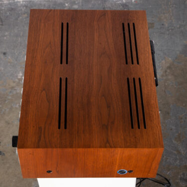
 Congratulations and thanks for the details. 1, Maitrikunj Building, Postal Colony, Opp. Do i have to connect it to the V- on psu or it has to be set free because i ha e a non-centered tapped toroidal? I agree to let Circuit Basics store my personal information so they can email me the file I requested, and agree to the Privacy Policy, Email me new tutorials and (very) occasional promotional stuff: The best post Ive ever seen on LM3886. Lets start by figuring out how much voltage and power your amplifier willneed from the power supply. Robert, Robert Buy a bigger case. First youllneed to calculatethe total power(Psupply)requiredby the amplifier. However If amp is run at near full load (not likely) heating effects of the transformer and bulk storage caps should be cooled as well. ); The distortion vanished when i shorted the diode with a piece of wire. Ill make the assumption its not a center-tapped transformer. And be sure to like, share, and subscribe if you found this helpful! I decided on a gain of around 27 db (22.4 Vo/Vi) for my amplifier. All at amazing prices when compared to what they would cost here if obtainable without custom order. Truly fantastic stuff you got here! The traces for the power supply feeds and power ground should berouted close together to reduce the loop area. I planned on usinga screwdriver shaft with a diameter of 11 mm to form the coil. I usually use the following cable (Mogami W2944) which is #26AWG for all my signal path wiring since its a shielded cable. Happy building! The main system ground connects to the ground protection circuit (discussed below), which then connects to the chassis. tuner reciever sansui thanks for sharing. Heres one of the PCBs: High currents flowing through the power supply and output traces will createmagnetic fieldsthat can generate currents in the feedback loop and input traces if theyre routed parallel to each other. Whoa !!! If possible please post on Power Supply, Speaker Protection, Soft Start and Pre-Amp. Relay contacts sometimes get worn/coated over time but youll only be having pre-amplified signal going through (not like relays for speaker protection). Get from a reputable supplier (components specialists rather than ebay). Looks like theres a new link to request the PS schematic https://www.circuitbasics.com/design-hi-fi-audio-amplifier-lm3886 Go to the Yellow box that starts with Bonus: download my parts list and click on the link for requesting the parts list. Im beginning to not trust this beast. PLUS Portable Rechargeable PA Amplifier Cube-28 With Speaker & Digital Media Player, PALCO 105 Guitar Amplifier with Gain, Black. Pete, yes this gainclone was a great project to build and the detailed theory was very instructive. I assembled the circuit exactly like the one in the guide, with the following changes in the PSU: 24-0-24 250 VA transformer and 4x 10000 uf 50V, having + -32.8 volts dc. Surprisingly, while searching for Negative Feedback of amps, I came here. your job is truly inspiring me so i have to do it. He sells them either blank or with the SMDs (surface mounted devices) already soldered in place (for an extra fee of course). Should I still include a ground loop protection circuit or is it not needed for this approach? These wires should be thick,as short as possible, and twisted together tightly. Second, Im trying to design the amp to go with a pair of Bose Interaudio 4000 speakers, which have a rating of 10-100W and 4-8 ohms. Thats a start. Do they have any kind of records on that so it may only require a push of a button on this end? Thediameter of 14 AWG is 1.62814 mm. The soundstage is still quite broad & airy but the bottom now seems a little richer. my other amp on same spaker calble pre amp is quit, Hey i would like to buy this PCB but dont know how to. The symbol indicatesthat the voltage is +30.2 V on the positive rail and -30.2 V on the negative rail.
Use a star ground design (look it up) since grounding to your chassis may or may not work correctly (painted surfaces sometimes dont conduct or connect correctly for a universal case ground. My amplifier is based off of thesame circuit providedin the datasheet, withall of the optional stability components included. The Left vs Right designations on the PS output are only to keep orderliness in wiring but its best to keep track of which wires are going to each board anyway so just follow the L vs R orderliness.
Rm and Cm create a time constant that slowly decreases the current at the mute pin when power to the amplifier is shutoff, and slowly increases the current when the amp isturned on. The Chassis terminal connects to the chassis: Click on the imagetoedit the layout, change component footprints, andorder the PCB. Great detail and explanations of the individual aspects of the circuit. Audio input cables from the source can pick up stray electromagnetic interference. If the Fc of this filter ishigher than the input filter, the amplifier will pass low frequencies to the feedback loop that itcant handle. I have a cd player and phono pre-amp with no volume control. trying to clone the gaincard which has a minimum number of parts. I put some changes in Powe supply Check the solder joint at Pin 8 of the LM3886. Keep in mind that a transformers voltage rating only tellsyou its AC voltage output. I would like to better understand how to set a value for low-frequency cutoff at the feedback loop. my 51pf silver mica is definitely much smaller than the 615pf silver mica I have so.? Ive already bought the pcb and the main electronics circuitry. 1) The Servo integrator cap (0.47uF) should have a large value resistor in parallel (~ 100 Meg), and not allowed to run open-loop in the real world. V+(L) / GND L = 25v , V-(L)/GND L =-25v Your email address will not be published. Peak Reverse Recovery Time 60ns Peak Non-Repetitive Forward Surge Current 100A I therefore decreased the value of the decoupling capacitor Cin to 0.4, which should increase the cut-off frequency to about 18 Hz; this produced a noticeable improvement. help please! tuner hh First off thank you for the great tutorial and the breakdown of each step. I would like a kit to same the time to order them. Please do refer our website: There are numerous designs for these circuits on the web. Like all the other, simple LM3886 or LM3875 gainclones Ive built the soundstage was magnificent, airy and brought detail to the music Ive never realized before with my regular amps & DAC combinations (nothing high end). * (stupid corrector). Dont you think that it is not good to have 4 or more coils close to circuitry or it may be disregarded? No Alessandro, thats not what I said if Im reading your response correctly. With a 680 pF capacitor, the Fc becomes: So a 680 pF capacitor will set the upper cutoff frequency to 234 kHz, which is close enough to my desired Fcof 250 kHz. At first, the sound stage seemed too narrow to me and some of the songs sounded somehow odd mostly metal tunes, in some the mids sounded somehow hollow.
Actual voltage is only in the equation as V-transformer and in the results. Thanks in advance. To reduce interference, keep the audio input and signal ground wires away from these parts or run them at 90 angles if separating them isunavoidable. If you still cant get it to work leave an email address here and Ill send them to you. Run to 8 ohm speakers But I dont understand why C4 (470F) is a polarised cap. The sound is now a little fuller at the bottom end than it was before with the proviso that I mostly listen to classical music and some better recordings of Folk & Blues. Is that right? Realistically. still experimenting. I have also learned to click every possible link when I cant find what I seek. Thanks a lot for this awesome project. Did I just miss a link or could you make them available. Yes, it matters a lot where the pot goes. Is your mains voltage calculation correct?
The best article ever. This step is important because if the transformers voltage is too low, the output power of the amplifier will be less than what you expected. Hi Jos, All other (47) pages of the article and the comments are hidden. Only one thing- why the pcb ordering link wont work anymore? Do you have a circuit diagram for this power supply? My power supply delivers + 34.5V 35.5 V to the amplifier end. Now after a couple of hours of listening to the LM3886 I must say it really sounds great! 1. With the knowledge and the tools available on this site I have built very modified boards. The production costs arent very high but the shipping costs are, unless you have a more local production facility. For TDA 2050: I was using this project for almost a year without any problem. I have seen in many audio amplifier, that the inductor L is wounded on resistor R. why you placed both component separate ? Oops, my bad. I hope youll make more of those overly detailed explanations, amazing knowledge source. Thanks for your advice to check the electrolytic caps also. Ive eliminated all the recommended decoupling caps and just used Nichicon FG 470uF 50V caps in C7&C8 while in the PS build Ive used four Nichicon 12000uF 50V caps (LKS1H123MESB). If these resistors vary much between the two channels, the gains will be different and one channel will be louder than the other. Ones the module is connected to the amp input, the hum vanishes, and Im left with a very clear sound. thank you so much for your posting of the parts list as well as the power supply schematic and values!! The idea is to keep the resistor leads as short as possible. If that does not fix it, try bypassing the Thiele network . Simone: I tested my amp boards using the chipamp PS and everything works fine. my toroidal is a 18v/9A per channel 9500ii I have sent you an email as I have some surplus boards. In my understanding there schould be an non polarised Cap, because there should be To tell you the honest truth I cant hear a big difference between the 18+18 and the 28+28 and the larger toroidals use doesnt improve the bass response. You can really feel it. The zener Diode i used is 9.1V zener diode. So I built this gainclone LM3886 chip amp and I learn a lot from doing it. The audio input wires and signal ground wires are the most sensitive to interference fromsurrounding magnetic fields. Should be only 25VDC going into each amp now. Martin. Hello To minimize inductance, locatethe Zobel network closeto the output pin (pin 4) and keep the traces short. You attached the chassis earth to the bottom plate of the case, but how are the top, front, sides and rear of the cases earthed? I will add a comment to this post: I calculated the total cost of accuiring these exact components in The Netherlands (europe): 80 (mouser) + 180 (hificollective) + 120 (modushop enclosure including heatsinks) + 50 (ebay/amazon/other) = 430, in total without pcbs. A470F capacitor will set the Fc of myfeedback loop filter to 4.9 times lower than the Fc of myinput filter. Im thankful of an Answer if I missunderstand something. Amit: I have to go back and look at the schematic, but if youve re-connected the power polar inputs inputs correctly onto to both the amps , and no sound is coming forth, that youve probably damaged the LM3886 chips. Now lets find a minimum VA rating for the transformer that will power youramplifier. The stereo should give me about 160W. The power supply and each of the individual components do have a massive influence, especially as there are so few of them. Welluse combinations of low pass and high pass filters to set the amplifiers bandwidth and improve stability. They are easily bent and the backs of the diodes will short if they touch together. Thank you! Before you can findthe required power supply voltage, you need to calculate the amplifiers peak output voltage. These calculations will tell youthe correctvoltage and VA ratings for thetransformer youll use to power youramp. Can I use Cin and Cc in The between of Rin and Rc?. Ive learned a lot from your detailed sections on build and theory. Like wise you can remove all electrolytics and test them as well (if you have a meter to do so). Use this formula to calculate the maximum supply voltage required by your amplifier: For my40 Watt amplifier, the maximum supply voltage it needsis: So mypower supply will need to deliver a peak voltage of30.2 V for my amplifier to output40 Watts into 6 speakers. It came out to just under $35 per side for the components, but you have to consider the costs for the boards and power supply. I will be using the amp/speaker setup for near-field purposes (mostly music with some gaming). thanks man. Alessandro: first thing I would do is contact the person who made the granny for you and ask them the secondary output wiring as a confirmation. Ciis also in the audio signal path, so a good quality capacitor should be used. From then on, I have been trying to improve its performance by making modifications. Wow! Thnx.. Hey, great job! Talk to you next time. I tested it all on a bench top so there was no common metal case joining the components. This setup drives them quite well. Cheers. Thank you. Simply adding some controls could decrease/alter the sound quality output, or not. It also adds a lot more weight to the assembled components in a chassis. Just be sure to stay well below 20 Hz or thebass will be weak. I have just finish the buikt Amp didnt work, but it was heating significantly. Its the best amp Ive ever owned by far. Then I rearranged the gain formula to solve for Rf1with a gain of 22.4 Vo/Vi: Im going to use Vishay-Dale PTF series metal film resistorsthroughout my amplifier, but the closest value I couldfind was20k. At the time of faulty connection both the fuse were blown up. The two silver mica capacitors (47pF and 680pF) appear to be reversed in your pictures. Hopefully my reply helps, if not whatever. I think I found a misbehaving (though physically intact) decoupling 22uf cap as a suspect and replaced it . Taking one amp board you could pull one leg of all the resistors and test to see if they have been affected. Rb before Rin or Rin before Rb? Tony, I think the author was using 1.1 as a factor in the calculation implying the mains voltage (=1) and adding 10% to it (10% of 1 is 0.1) hence the factor is 100% + 10% = 1.1. Thank you for this really great article. None of the decoupling caps blown, neither any physical damage to IC. Pls make thesis on power supply too. Im wondering where we can add bass control and volume control in this. So, my Rm will need to be less than 54k for the current atpin 8 to be greater than0.5 mA. A request .Could you also consider doing a solid state discrete power amp with dual dc power supply. Heres one channel of my amplifier attached to a properly sized heat sink: Now that youve calculated the power supply and heat sink requirements, the next step isto find values for the components in the amplifier circuit. Thank you very much this blog is very helpful. V+(L) / GND L = 25v , V-(L)/GND L =-25v The drawback is a bigger tolerance (10%), but they are dirt cheap compared to the Mundorf monster cap used here (WIMA MKP4F044706F00KSSD is about 1/7 of the price and way easier to find where I live). Due to the length of this post, I decided not to cover the power supply in detail, but I may do so in the future. headphone amplifier end hi 27th fi meet london head april The heat sink will dissipate the peakpower produced by the amplifier (Pdmax) if its thermal resistance (sa) is less than or equal to the value calculated with this formula: The LM3886 is manufacturedin two different packages, the LM3886T and the LM3886TF. The Gerbers for the amp PCBs is a bit circuitous now. The finished boards look great. this is where i have 50v. Im just missing the mundorfs and the toroidal. The result was good, but not yet satisfactory, all a bit pointless without sensitive speakers to match. Is it worth doing it or i should buy a 182/330VA ? Thermal paste has a thermal resistance of around0.2 C/W, but the exact value of the type you use should be available from the manufacturer. This is the best explained I ever came across. 60/40 solder has a wide melting range, and when itsat the lower end of therange it becomes pasty. Beautiful job. When you convert the transformers AC voltage to DC on the power supply, the voltage actually increases to about 25V due to the bridge rectifier. This produces a soft start/stop effect that gradually increases or decreases the volume instead of abruptly cutting it. Or average the impedance out at 6 Ohms? If you built the PS as in this article then grey + grey goes to either VAC1 + OV1 or VAC2 + OV2 and black + black would go to the whichever set you didnt use for the grey + grey. The bass is verydeep and clean. Amit: as a quick check, jumper D1 so the diode is taken out of the circuit and see if you get sound again before going through the hassle of replacing the LM3886. The individual ground networks are connected to the main system ground so thathigher current grounds arecloser to the reservoir capacitors. We havemore tips and tricks on designing PCBsin ourHow to Make a Custom PCBarticle, so check that out if youre interested. sa: The thermal resistance from the heat sink to the ambient air. cs: The thermal resistance of the gap between the chip case and the heat sink. happy with outcome I also really like how you supplied the calculations for determining the size of the components. I made an amp with LM3876 in 2015. many thanks for the great job. Number of Elements per Chip 1 If you put one on the amps output its got to be a huge, well insulated one to withstand the power output from the amp (I think these are called L-pads). Each one has its own electrically isolated ground plane on the bottom layer. Any chance we can get a copy of the gerber files and BOM. Though I have no expertise in Physics, was able to understand the technical things in this article. If the latter: Are there any benefits (audio signal quality or other reason) with axial capacitors with such big plates? this is unexpected to me because i was expecting to have 32 volts to feed the amp To separatethelow currentgrounds from the high current grounds, we willcreate several ground networks: These grounds should connect only once at a set of terminals called the main system ground. And sorry for asking such an obviously stupid question. Thank you for your excellent work on this guide. Im glad to say that after shorting the Zener D1, I can now get sound at the output. I signed up for the partslist but I am not recieving any partslists, can someone upload the partslist, thank you. In this tutorial, Ill go step by step throughthe amplifier design process as I builda 40 Watt stereo amplifier usingthe LM3886. I cant thank you enough. Thanks. Peak Reverse Recovery Time 50ns The right channel PCB is mounted upside down so that the input side of the board is close to the RCA and 3.5 mm input terminals. And now I am left with these choices. If I may offer my observations, which are purely subjective though based and no doubt influenced by research. Mains voltages can vary up to 10% depending on your location. Im going to test the amp PCB build with other types of nichicon 470uF caps at C7&C8 as well as trying different brand caps at C5 to see how the sound changes. 2. Looking through Mouser for a non-polar cap (470uF 50V) turned up a Panasonic and a few Nichicons but Im not sure they possess good musicality as some folks might say.you need in the music signal path. Electrolytics, ceramics, and tantalum capacitors should be avoided. Research by Tom Christiansenshows that a 4.7 F ceramic X7R capacitor in parallel with a 22 F electrolytic and 1000F electrolytic has significantly better performancethan the paralleled 100 nF, 10F, and 470F capacitorsrecommended in the datasheet. They should be located away from the amplifiers input circuitry to prevent interference from the magnetic fields generated by the inductor. thanks for sharing. Usually the trans that is stated to be 18V runs a little higher, maybe 19-20V so 19+19V = 38V then times 1.4 = 53V. an symetrical Audio Signal, so this Cap would be about half the time wrong polarised. . Unfortunately, it alsoincreases the chance foroscillation. The amp needs about +-30V DC though. It will be the last big step but i need time to save some money. A typical value for Tambis room temperature (25C). Best tutorial youve ever made and one of the best available online. Doing your maths, i should have a 219,34 volts/370 VA toroidal to get 68 watts. I recently did some comparisons with some other amps, and I find my gainclone is quite slow in the deep bass, not very dynamic, so Im trying to improve it. the grounfg loop same but I put other capcitor value 200nf (I got one in my box) Just in case its not clearly stated in the history flow above, my changes to the decoupling caps are 470uF/50V nichicon KAs, 10uF/100V Silmic IIs (mounted on underside of board) and Vishay 100nF/100V 1837MKPs (mounted on top with a bit of creative angling). This difference in voltage will beamplified as noise. Although its a bit more work, I prefer the T version for the 0.8 C/W increase over the other. Regulation valuescan usually be found in the transformers datasheet, but if you dont knowyour transformers regulation, a safe value to use is 15%. Best, If the muting circuit is not getting its necessary current to shut off no sound will be generated. Then it will ask you if you want to check the file before generating the Gerberssay YES. trodial transformer 25-0-25 (i use 8 ohm speakers) Heres the final schematic: Note: The component labels matchthe labels on the PCB layout provided below. You can click on the image aboveto edit the PCB layout, change the component footprints, and order PCBs. i am not sure how that will be done though. NASEOH, Chembur Maitrikunj Building Mumbai - 400071, Maharashtra, India, Carry Bags and Multiutility Bags & Pouches, Shop No. You can add an input selector knob (if you want more inputs) on the same controls-pcb and then mount the pcb parallel to where your control knobs should be. I tend to listen tomusic with lots ofbass, so I decided on a fairlylow Fcfor my amplifier. Sascha. Rb and Cc form a low pass RC filter that sets the upper limit of the amplifiers bandwidth at the non-inverting input: In the datasheet, Cc is shown connected betweenthe non-inverting input andthe inverting input.
so investigating more I found that setting a low cutoff frequency <5 Hz is not good at all; <20 Hz is not audible, but some sources produce lower frequencies that draw a lot of power unnecessarily, lowering dynamics and making the bass muddy. Saw down the heatsnk. Hanger the IC ?? THANK YOU. cmoy vr2xmq steve case shf af through What do you think of these changes? Yuval. Entering this information into the inductance calculator, I found Id need about12 wraps to get a 0.7 Hinductor. The rest of the pairs of GND connections are SPK GND, PWR GND, SIG GND and IN GND. I could send them to you for the amount of the postage. Awesome writeup, many thanks! It just does not get better than that! Unfortunately no sound comes out.
Thank you very much for your help which I really appreciate. As C13 is used to stabilize the amplifier I would just like confirmation that the parts list and silkscreen are correct.
I have just been testing only one board. troidial 24 0 24 with 6 /8200uf nichicon the pins on the chip are so close and also i dont see this in the video. There are two schools of thought here. Two things: short the D1 zener (jumper it) taking it out of the muring circuit.
Should I use 4 Ohms as my base for the power calculations? My guess is that the fault lies with the amp chips. What have others done to resolve this ?
For the hum issue, Ill try the suggestions you listed above. I ordered exactly the chassis and heatsink as specified and there is no way that the heatsink will fit in that chassis. Pete Zafian on October 27, 2020 at 1:13 pm The DC voltagewill be higher after the bridge rectifier diodes on yourpower supply convert the AC voltage to DC. I would really appreciate any help before I take every component one after the other. Might be a bit expensive to ship, Im guessing $20-25. Hi all The Fc with a4.7 F capacitor would be: An Fc of 1.69 Hz is pretty close to my desired 1.5 Hz, so a 4.7F capacitor should be good.
The LM3886 is an excellent component and you explained who to do better. Try to avoid the standard 60/40 tin lead solder and use a 63/37 eutectic solder instead. Note that the chassis MUSTbe electrically connected to the mains earth wire to prevent mains voltages on the metal chassis in the event of a fault. Any space between the wires of the same circuitwill create a loop that cantransmit or receive electromagnetic fields. From the left Since the power supply is relatively far away from the chip, inductance and resistanceare a problem. The PS design is lacking only in that it never incorporated any LED indicators that it was actually On. Actually you can create a non polarized cap by putting to polarized back to back, i.e. Did you mean X7R ceramic capacitors. 3-Rb,Rin,Cc What is your household voltage, 110-120VAC or 220-230VAC? The minimum size of the heat sink can be found by calculating itsmaximum thermal resistance (inC/W). 4-Cin,Rin,Rb,Cc However the big lytics will continue to conduct until fully discharged and continue to do damage for faulty down stream components. I cant hear a difference with the Thiele network in place or not, so I just left it off. The resistor reduces this current and breaks the ground loop. I like the way you treat ground connections. As an electrical engineering student, I love getting the chance to truly understand the process of creating the design. based on the typical application of the datasheet, Thanks Hicoco.Dave: youll have to join the diyaudio forum and then private Message (PM) Dario Fremen (ClaveFremen) about purchasing the boards directly from him in Italy. I really think 2 amp or 21/2 amp would work really well, but did not have them in stock at the time. Best, I really enjoyed reading this awesome guide! Robert. The LM3886 needs a heat sink large enough to dissipate the heat it generates or it will quickly becomedamaged. However , is it possible to go directly to EDA with info you posted for the amplifier board? The ones that are completely encased in black plastic are insulated and cant be shorted but the other types have metal exposed (on the back; presumably for heat transfer or for grounding purposes) but in this bridge rectifier circuit the metal-backed ones cant touch, ok thanks again looking forward to finally building this sourcing the components was not as easy as i would have liked, Hi all..I just wanted to know the difference betweeen a center tapped (+25) 0 (-25) torroid and a (+25)-0 (-25)-0 torroid.