"Vena Contracta" is the minimum jet area that appears just downstream of the restriction. If you have not yet determined the orifice size then to estimate this we would suggest that you temporarily use a Flow Control Valve in your system to control the flow rate in the pipe (to whatever flow rate you require). Reference number: ISO 5167-1:2003. Our goal is to make science relevant and fun for everyone. orifice  Learn more about our: HEADQUARTERS SFC KOENIG AG Lagerstrasse 8 8953 Dietikon, Switzerland Phone +41 44 743 46 00 sfc-info-ch@idexcorp.com, EUROPE SFC KOENIG GmbH Max-Eyth-Strasse 14 89186 Illerrieden, Germany Phone +49 7306 2062 300 sfc-info-de@idexcorp.com, AMERICAS SFC KOENIG LLC 73 Defco Park Road North Haven, CT 06473, USA Phone +1 203 245 1100 sfc-info-us@idexcorp.com, ASIA SFC KOENIG Flow Control (Suzhou) Co., Ltd. No.51 TangBang Road, CaoHu Boulevard Xiang Cheng District, Suzhou, China. 0000043336 00000 n
pressure drop orifice flow restrictor through there The flow coefficient Cf is found from experiments and is tabulated in reference books; it ranges from 0.6 to 0.9 for most orifices. 0000001346 00000 n
In the venturi meter the fluid is accelerated through a converging cone of angle 15-20o and the pressure difference between the upstream side of the cone and the throat is measured and provides a signal for the rate of flow. Any flow Validated component will be supplied with a Certificate of Validation report containing traceable standards used, test conditions, measurement results and inspection sign off. Currently, I work in a reputed MNC as a Senior Piping Stress Engineer. 0000001577 00000 n
Measurement of fluid flow using small bore precision orifice meters. For an area ratio of 0.5 the head loss is about 70 - 75% of the orifice differential. endstream
endobj
10 0 obj<>>>/Filter/Standard/O($/DZ%@{6m7)/P -3392/R 4/U(FaGk" )/V 4/EncryptMetadata false/StrF/StdCF/StmF/StdCF>>
endobj
11 0 obj<>
endobj
12 0 obj<>/MediaBox[0 0 612 792]/Resources 13 0 R/Type/Page>>
endobj
13 0 obj<>
endobj
14 0 obj<>
endobj
15 0 obj<>stream
The venturi tube is suitable for clean, dirty and viscous liquid and some slurry services. Thanks for posting.I have started using RW Miller flow consultant. 0000016310 00000 n
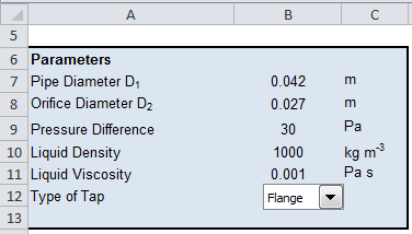
Please enter some basic details into our Orifice Size Calculator form below to estimate the orifice size needed in mm. The flow area is at a minimum at the throat. It should be noted that this standard practice is applicable to single-phase fluids only. All flow calibrated components are measured on instruments that are calibrated with Lenox Laser traceable standards. Calculated dO shall be replaced with previous dO and repeat step to step until the dO agrees with calculated dO. This change can be used to measure the flowrate of the fluid. flow orifice water through gas liquid estimated guides calculate orifice calculating flow equation rate pressure calculation horizontal air
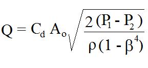
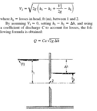
The formula above can be used with limitations for applications with relatively small changes in pressure and density. where Ao is the area of the orifice. The specific gravity of kerosene is 0.82. 2022 Leaf Group Ltd. / Leaf Group Media, All Rights Reserved. The Orifice plate is a very robust flow measurement device. I have a doubt for Multistage RO, Is the flow rate changes after each stage or will it be the same at final stage? The text is good as well as the formulas but in order to be useful, each parameters has to be defined and the unit in which it has to be used defined. In the case of a simple concentric restriction orifice the fluid is accelerated as it passes through the orifice, reaching the maximum velocity a short distance downstream of the orifice itself (the Vena Contracta). if(typeof ez_ad_units!='undefined'){ez_ad_units.push([[300,250],'whatispiping_com-banner-2','ezslot_8',851,'0','0'])};if(typeof __ez_fad_cmd!='undefined'){__ez_fad_cmd.push('div-gpt-ad-whatispiping_com-banner-2-0');}else{__ez_fad_cmd=['div-gpt-ad-whatispiping_com-banner-2-0'];};report this ad, Guidelines for sizing of Restriction Orifice for single-phase fluids (With PDF). In order to avoid cavitation problem, the minimum allowable value of cavitation index, Kd, should be selected based on the following: (1) Cavitation index Kd=0.37 shall be used for the usual case. The ideal equation (3) can be modified with a discharge coefficient: q = cd A2 [ 2 (p1 - p2) / (1 - (A2 / A1)2) ]1/2 (3b), The discharge coefficient cd is a function of the jet size - or orifice opening - the, Avc = area in "vena contracta" (m2, ft2). 0000050779 00000 n
0000061707 00000 n
0000029319 00000 n
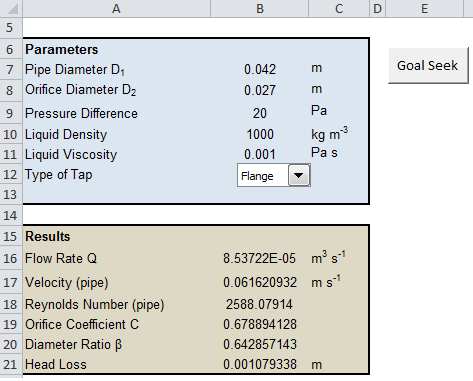
If you want to promote your products or services in the Engineering ToolBox - please use Google Adwords. When the system is solved the calculated results will report the additional pressure drop that the FCV (Flow Control Valve) had to introduce in order to control the flow rate (just hover over the FCV with the mouse cursor and the Control Loss will be shown). 0000001096 00000 n
American Society of Mechanical Engineers (ASME). You can find typical values in our article on discharge coefficients for nozzles and orifices. 9 0 obj <>
endobj
The safe way to install restriction orifices, Overview of Piping Instrument Interface: An article, Articles Related to Piping Interface Departments, For liquid service: density, vapor pressure, For vapor service: molecular weight, Cp/Cv, Z-factor, viscosity, Inlet and outlet pressures of each orifice, The pressure at vena-contracta of each orifice, Calculated cavitation index of each orifice. The Pipe Flow Expert software does not currently contain a specific orifice component. Divide the flow of the liquid by the velocity of the liquid to determine the area of the orifice in square feet. Welcome to my space, I am Anup Kumar Dey, an experienced piping engineer for the last 19 years. Click here to recapitulate those before proceeding for actual RO sizing steps. The following notes explain how to model and size an orifice.
Learn more about our: HEADQUARTERS SFC KOENIG AG Lagerstrasse 8 8953 Dietikon, Switzerland Phone +41 44 743 46 00 sfc-info-ch@idexcorp.com, EUROPE SFC KOENIG GmbH Max-Eyth-Strasse 14 89186 Illerrieden, Germany Phone +49 7306 2062 300 sfc-info-de@idexcorp.com, AMERICAS SFC KOENIG LLC 73 Defco Park Road North Haven, CT 06473, USA Phone +1 203 245 1100 sfc-info-us@idexcorp.com, ASIA SFC KOENIG Flow Control (Suzhou) Co., Ltd. No.51 TangBang Road, CaoHu Boulevard Xiang Cheng District, Suzhou, China. 0000043336 00000 n
pressure drop orifice flow restrictor through there The flow coefficient Cf is found from experiments and is tabulated in reference books; it ranges from 0.6 to 0.9 for most orifices. 0000001346 00000 n
In the venturi meter the fluid is accelerated through a converging cone of angle 15-20o and the pressure difference between the upstream side of the cone and the throat is measured and provides a signal for the rate of flow. Any flow Validated component will be supplied with a Certificate of Validation report containing traceable standards used, test conditions, measurement results and inspection sign off. Currently, I work in a reputed MNC as a Senior Piping Stress Engineer. 0000001577 00000 n
Measurement of fluid flow using small bore precision orifice meters. For an area ratio of 0.5 the head loss is about 70 - 75% of the orifice differential. endstream
endobj
10 0 obj<>>>/Filter/Standard/O($/DZ%@{6m7)/P -3392/R 4/U(FaGk" )/V 4/EncryptMetadata false/StrF/StdCF/StmF/StdCF>>
endobj
11 0 obj<>
endobj
12 0 obj<>/MediaBox[0 0 612 792]/Resources 13 0 R/Type/Page>>
endobj
13 0 obj<>
endobj
14 0 obj<>
endobj
15 0 obj<>stream
The venturi tube is suitable for clean, dirty and viscous liquid and some slurry services. Thanks for posting.I have started using RW Miller flow consultant. 0000016310 00000 n
Please enter some basic details into our Orifice Size Calculator form below to estimate the orifice size needed in mm. The flow area is at a minimum at the throat. It should be noted that this standard practice is applicable to single-phase fluids only. All flow calibrated components are measured on instruments that are calibrated with Lenox Laser traceable standards. Calculated dO shall be replaced with previous dO and repeat step to step until the dO agrees with calculated dO. This change can be used to measure the flowrate of the fluid. flow orifice water through gas liquid estimated guides calculate orifice calculating flow equation rate pressure calculation horizontal air
The formula above can be used with limitations for applications with relatively small changes in pressure and density. where Ao is the area of the orifice. The specific gravity of kerosene is 0.82. 2022 Leaf Group Ltd. / Leaf Group Media, All Rights Reserved. The Orifice plate is a very robust flow measurement device. I have a doubt for Multistage RO, Is the flow rate changes after each stage or will it be the same at final stage? The text is good as well as the formulas but in order to be useful, each parameters has to be defined and the unit in which it has to be used defined. In the case of a simple concentric restriction orifice the fluid is accelerated as it passes through the orifice, reaching the maximum velocity a short distance downstream of the orifice itself (the Vena Contracta). if(typeof ez_ad_units!='undefined'){ez_ad_units.push([[300,250],'whatispiping_com-banner-2','ezslot_8',851,'0','0'])};if(typeof __ez_fad_cmd!='undefined'){__ez_fad_cmd.push('div-gpt-ad-whatispiping_com-banner-2-0');}else{__ez_fad_cmd=['div-gpt-ad-whatispiping_com-banner-2-0'];};report this ad, Guidelines for sizing of Restriction Orifice for single-phase fluids (With PDF). In order to avoid cavitation problem, the minimum allowable value of cavitation index, Kd, should be selected based on the following: (1) Cavitation index Kd=0.37 shall be used for the usual case. The ideal equation (3) can be modified with a discharge coefficient: q = cd A2 [ 2 (p1 - p2) / (1 - (A2 / A1)2) ]1/2 (3b), The discharge coefficient cd is a function of the jet size - or orifice opening - the, Avc = area in "vena contracta" (m2, ft2). 0000050779 00000 n
0000061707 00000 n
0000029319 00000 n
If you want to promote your products or services in the Engineering ToolBox - please use Google Adwords. When the system is solved the calculated results will report the additional pressure drop that the FCV (Flow Control Valve) had to introduce in order to control the flow rate (just hover over the FCV with the mouse cursor and the Control Loss will be shown). 0000001096 00000 n
American Society of Mechanical Engineers (ASME). You can find typical values in our article on discharge coefficients for nozzles and orifices. 9 0 obj <>
endobj
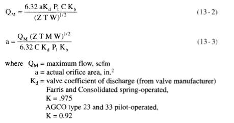
The safe way to install restriction orifices, Overview of Piping Instrument Interface: An article, Articles Related to Piping Interface Departments, For liquid service: density, vapor pressure, For vapor service: molecular weight, Cp/Cv, Z-factor, viscosity, Inlet and outlet pressures of each orifice, The pressure at vena-contracta of each orifice, Calculated cavitation index of each orifice. The Pipe Flow Expert software does not currently contain a specific orifice component. Divide the flow of the liquid by the velocity of the liquid to determine the area of the orifice in square feet. Welcome to my space, I am Anup Kumar Dey, an experienced piping engineer for the last 19 years. Click here to recapitulate those before proceeding for actual RO sizing steps. The following notes explain how to model and size an orifice.  0000001652 00000 n
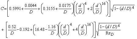
This is necessary to complete the analysis of course. ), ( Few More Handpicked Learning Resources for you, The safe way to install restriction orificesLevel Gauges for Industrial ApplicationsOverview of Piping Instrument Interface: An articleBasics of Piping Design and LayoutPiping Stress Analysis BasicsPiping Material BasicsArticles Related to Piping Interface Departments. Calculate cavitation index, Kd by equation (15), and compare with minimum allowable value. Through this platform, I will share my experiences and knowledge with you in an innovative way. The total area of the orifice would be 4 square feet. These relationships all utilise the parameter There are in general three methods for placing the taps. All Rights Reserved. The velocity of the liquid in the system described in Step 1 might be 2 feet per second, for example. Please read AddThis Privacy for more information. In a flow metering device based on the Bernoulli Equation the downstream pressure after an obstruction will be lower than the upstream pressure before. A fluid passing though an orifice constriction will experience a drop in pressure across the orifice. Two key limitations include: (a) Differential Pressure across the orifice plate, 2009 - 2022 instrumentationtoolbox.com. But opting out of some of these cookies may affect your browsing experience. 19 Fluid Meters Their Theory And Application- Sixth Edition, The flow nozzle is recommended for both clean and dirty liquids. The mass flowrate can be found by multiplying Q with the fluid density. This article will provide the guidelines for the sizing of Restriction Orifice. After the metering device the velocity will decrease to the same level as before the obstruction. orifice meter coefficient equation flow discharge venturi rate calculation calculate through iso nozzle spreadsheets excel calculations passing Write down the flow of the liquid that will be going through the piping system in cubic feet per second. Thus K = (Head loss x 2g)/(v^2)
For a given geometry (A), the flow rate can be determined by measuring the pressure difference p1 - p2. Get the latest news and insights on sealing and flow control.
0000001652 00000 n
This is necessary to complete the analysis of course. ), ( Few More Handpicked Learning Resources for you, The safe way to install restriction orificesLevel Gauges for Industrial ApplicationsOverview of Piping Instrument Interface: An articleBasics of Piping Design and LayoutPiping Stress Analysis BasicsPiping Material BasicsArticles Related to Piping Interface Departments. Calculate cavitation index, Kd by equation (15), and compare with minimum allowable value. Through this platform, I will share my experiences and knowledge with you in an innovative way. The total area of the orifice would be 4 square feet. These relationships all utilise the parameter There are in general three methods for placing the taps. All Rights Reserved. The velocity of the liquid in the system described in Step 1 might be 2 feet per second, for example. Please read AddThis Privacy for more information. In a flow metering device based on the Bernoulli Equation the downstream pressure after an obstruction will be lower than the upstream pressure before. A fluid passing though an orifice constriction will experience a drop in pressure across the orifice. Two key limitations include: (a) Differential Pressure across the orifice plate, 2009 - 2022 instrumentationtoolbox.com. But opting out of some of these cookies may affect your browsing experience. 19 Fluid Meters Their Theory And Application- Sixth Edition, The flow nozzle is recommended for both clean and dirty liquids. The mass flowrate can be found by multiplying Q with the fluid density. This article will provide the guidelines for the sizing of Restriction Orifice. After the metering device the velocity will decrease to the same level as before the obstruction. orifice meter coefficient equation flow discharge venturi rate calculation calculate through iso nozzle spreadsheets excel calculations passing Write down the flow of the liquid that will be going through the piping system in cubic feet per second. Thus K = (Head loss x 2g)/(v^2)
For a given geometry (A), the flow rate can be determined by measuring the pressure difference p1 - p2. Get the latest news and insights on sealing and flow control.
0000064883 00000 n excel orifice flow meter asme calculator spreadsheet liquid calculations bore mfc 14m 2001 diameter 0000029109 00000 n orifices edge simple flow orifice 0000051493 00000 n Very good writeup but it appears Equation 15 to calculate Kd is not defined. In the above example, you would divide 8 by 2. Downstream of the Vena Contracta in the recovery zone, the fluid decelerates converting excess kinetic energy into pressure as it slows. orifice connector hose (2) On some occasion such as the following cases, use Kd=0.93 as an incipient cavitation condition in order to avoid severe economical risk. 0000044530 00000 n Out of these, the cookies that are categorized as necessary are stored on your browser as they are essential for the working of basic functionalities of the website. 0000044111 00000 n Hello,Really useful text. Orifice diameter (dO) shall be calculated by equation (13). The same article also lists the important factors on which the sizing of a restriction orifice depends. 5 and can be used to calculate mass flow through an orifice. Some of our calculators and applications let you save application data to your local computer. (3) The calculated hole diameter of RO should be rounded to the conservative size for easy manufacturing. %%EOF In the case of the multi-stage restriction orifice, the minimum distance, as shown below, should be provided between orifices, to avoid the reduction in RO performance. It is one device that is very easy to use and can easily be adaptable to many flow measurement applications. flow orifice rate gas through oil area required valve given obtained separator relief orifice plate flow meter bore basics diameter ratio edge square sharp In case If any changes occur, how to calculate the flow rate at each stage? To calculate the flowrate of a fluid passing through an orifice plate, enter the parameters below. This website uses cookies to improve your experience while you navigate through the website. Semiconductors, medical equipment, lasers, optics and aviation and aerospace. 7 0000015694 00000 n Cookies are only used in the browser to improve user experience. orifice calculations coefficient meter discharge notation equations These cookies will be stored in your browser only with your consent. For support please contact us, or request a quote for a Series RE flow restrictor for your application. Hi. Currently using 4mm orifice in a system to produce a flow of 760m3/h.The 4mm orifice is prone to fouling and clogging alot. Dear Anup,I read your blogs on various technical subjects and those are really useful to us. Production and Challenges of Green Steel (PDF), link to What is a Concrete Pipe? 22 keep it up.. VYAY KRUTE VARDHTE EVANM NITAYM VIDHYA DHANAM SARVA DHANAM PRADHANAM More you spend more it will be that is Knowledge.. orifice pressure drop through calculating flow nozzle physics accurately defined 900cc scenario specific min where These cookies do not store any personal information. Since the pressure at 1 will be higher than the pressure at 2 (for flow moving from 1 to 2), the pressure difference as defined will be a positive quantity. Since it depends on the orifice and pipe diameters (as well as the Reynolds Number), one will often find Cf tabulated versus the ratio of orifice diameter to inlet diameter, sometimes defined as b. The theoretical flow rate q will in practice be smaller (2 - 40%) due to geometrical conditions. startxref The deflection ratio of the eccentric orifice e is 0.75. The K here (as above) is actually a Fitting K Factor. The discharge coefficient When the fluid has decelerated and returned to the normal bulk flow pattern the final downstream pressure has been reached. The diameter ratio can be calculated to. (The default calculation involves air passing through a medium-sized orifice in a 4" pipe, So be with me for the next couple of years! NOTE: If the 'Orifice Size' is larger than the maximum plug size text please select a larger restrictor body size or reduce the flow rate. Its cost of operation is minimal and familiarity with the device is near universal. Orifice diameter (dO) shall be calculated by equation (13) using assumed upstream pressure. Hi, Thank you for your useful information.If it is possible to design Orifice in Sonic and Subsonic conditions, which one of the two do you suggest? The equation can be adapted to vertical flow by adding elevation heights: p1 + 1/2 v12 + h1 = p2 + 1/2 v22 + h2 (1b), = specific weight of fluid (kg/m3, slugs/ft3), Assuming uniform velocity profiles in the upstream and downstream flow - the Continuity Equation can be expressed as, q = v1 A1 = v2 A2 (2). Due to the Benoulli and the Continuity Equation the velocity of the fluid will be at it's highest and the pressure at the lowest in "Vena Contracta". 0000061095 00000 n Reference number: ISO 5167-1:2003. International Organization of Standards (ISO 5167-1) Amendment 1. Our expert team is experienced in a wide range of automotive, fluid power and specialty applications. Concrete pipes are pipes made from concrete. AddThis use cookies for handling links to social media. 1998. orifice pressure plate drop flow calculator calculation equation venturi rate substituting ), ( What is Green Steel? %PDF-1.6 % These applications will - due to browser restrictions - send data between your browser and our server. Can you define what k and C1 are referring to exactly? All these pluses make the Orifice plate the first choice measurement device in almost every flow application. How are these method differs in sizing the bore in the sizing of restriction orifice? orifice calculator flow gas meter maplesoft aspx 0000060386 00000 n This article provides calculation methods for correlating design, flow rate and pressure loss as a fluid passes through a nozzle or orifice. In our last article we have discussed regarding restriction orifices in details. An orifice with diameter D2 = 50 mm is inserted in a 4" Sch 40 steel pipe with inside diameter D1 = 102 mm. Therefore, it should not be necessary to take a straight run of piping both upstream and downstream of RO to keep performance. The following is a summary of input data to be prepared for the design of RO: (3) Minimum allowable value of cavitation index for liquid service. 0000049997 00000 n The components packaging will be individually labeled with Part Description, Flow Direction, Flow Reading (SCCM, SLPM, TORR), size in microns, and date. 1 If the cavitation index equals to or slightly bigger than 0.37 (or 0.93), the design of the first stage RO is completed and go to step . 0000060195 00000 n No certification is included. Repeat the steps from to , until the cavitation index is equivalent to the minimum allowable value. His work has appeared in a wide range of online and print publications across Canada, including Atlantic Business Magazine, The Grid and Halifax Magazine. Note! Assuming a horizontal flow (neglecting the minor elevation difference between the measuring points)the Bernoulli Equation can be modified to: p1 + 1/2 v12 = p2 + 1/2 v22 (1). Material is high grade such as stainless steel or higher and pipe size is larger than 12. If cavitation index < 0.37 (or 0.93), decrease the upstream pressure and repeat the steps from to . ASME MFC-14M-2001. Production and Challenges of Green Steel (PDF). Types and Applications of Concrete Pipes (PDF). 0000028738 00000 n through flow orifice equation bernoulli submerged orifices engineeringcivil orifice diameter excel parameters calculations 11 f_ac)ZQh7~[k2Ic3. We Provide Tools and Basic Information for Learning Process Instrumentation and Control Engineering. With 5+ billion parts installed and failure rates <1 PPM, SFC KOENIG is recognized as a global leader in sealing and flow control. Equation (4) can be modified to mass flow for fluids by simply multiplying with the density: m = cd ( / 4) D22 [ 2 (p1 - p2) / (1 - d4) ]1/2 (5). Please provide me in detail information regarding above as I am working on same research area. You also have the option to opt-out of these cookies. Set the upstream pressure of (n-1)-th stage orifice for the downstream pressure of n-th stage orifice. The orifice calculator is based on eq. Towers, turbines, gearboxes; processes for shaping and finishing component parts. Equation (3) can be modified with diameters to: q = cd ( / 4) D22 [ 2 (p1 - p2) / (1 - d4) ]1/2 (4), D2 = orifice, venturi or nozzle inside diameter (m, ft), D1 = upstream and downstream pipe diameter (m, ft). In extreme cases this may lead to cavitation when the local pressure is less than the vapour pressure of a liquid. There are a few reasons why you might want to install an orifice, which include increasing the line pressure and decreasing the flow through the line. Tolerances will be the same as listed. It is defined as: \displaystyle Y = \frac{C_{d,c}}{C_{d,i}}. Incompressible coefficient of contraction CCi shall be calculated by equation (7). You can however model an orifice by using a Fitting with the appropriate K factor or by using a Component with defined flow versus pressure loss performance. For a pressure difference of 1 kPa (0,01x10⁵ N/m2) - the theoretical flow can be calculated: q = (0.002826 m2) [2 (0.01 105 N/m2) / (820 kg/m3)(1 - ( (0.002826 m2) / (0.00785 m2) )2)]1/2. orifice We don't collect information from our users. Google use cookies for serving our ads and handling visitor statistics. flow orifice swagelok meter rate through calculations principles company calculated diameter pipe dimensions fig fixed engineer baxter ulrich explain determine 0000001996 00000 n The expansion factor I need some help understanding the sizing orifice bore in cavitating flow and thick orifice in cavitating flow. Add standard and customized parametric components - like flange beams, lumbers, piping, stairs and more - to your Sketchup model with the Engineering ToolBox - SketchUp Extension - enabled for use with the amazing, fun and free SketchUp Make and SketchUp Pro .Add the Engineering ToolBox extension to your SketchUp from the SketchUp Pro Sketchup Extension Warehouse! RegardsAbhishek Talageriabhicvsit@gmail.com, Your email address will not be published. 0000015509 00000 n
Powered by, ( You can represent an orifice in a Pipe Flow Expert system by using a Fitting with a specific K factor if you know the K factor that represents the flow versus pressure loss performance of your orifice. RO is applied to regulate the flow rate or pressure. The accuracy strongly increases in the lower part of the operating range. orifice coefficient calculation liquids Due to the non linearity the turn down rate is limited. 0000050182 00000 n Compare the assumed d0 with the calculated dO in step . A discharge coefficient cd = 0.975 can be indicated as standard, but the value varies noticeably at low values of the Reynolds number. 215131 Phone +86 512 6585 9515 sfc-info-cn@idexcorp.com. Equivalent_K_Factors_For_Sharp_Edged_Orifices.pdf ), ( orifice excel diameter parameters calculations reynolds ok soon give operating specific \Delta z = z_{1} - z_{2}, the following head loss and flow rate equations may be used: \displaystyle Q = C_{d}A_{o}Y\sqrt{\frac{2\left(\Delta P + \rho g \Delta z \right)}{\rho\left(1-\beta^{4}\right)}}, \displaystyle Q = C_{d}A_{o}Y\sqrt{\frac{2g\left(\Delta h+\Delta z \right)}{\left(1-\beta^{4}\right)}}, \displaystyle \Delta P = \frac{1}{2} \rho \left(1-\beta^{4}\right) \left( \frac{Q}{C_{d}A_{o}Y}\right)^{2} - \rho g \Delta z, \displaystyle \Delta h = \frac{1}{2g} \left(1-\beta^{4}\right) \left( \frac{Q}{C_{d}A_{o}Y}\right)^{2} - \Delta z. Based in Halifax, Nova Scotia, Jordan Whitehouse has been writing on food and drink, small business, and community development since 2004. Where v is the velocity in the pipe. 5 Assume upstream pressure of the first stage orifice.
Our flow products and custom components are measured in three different tiers: All standard orifice components are optically measured on instruments that are calibrated with Lenox Laser traceable bar chart standards. To account for this effect, a discharge coefficient Cd is introduced into the above equation to marginally reduce the flowrate Q. 15 How OEM's can make their parts better, faster, and more efficient. ), Learning Instrumentation And Control Engineering, Industrial Motor Starters and Starting Methods, Electrical Protection of 3 phase Motors: Types and Protection Schemes, Understanding the Technical Specifications on the Nameplate of Solar Panels, A Guide to Solar Panels Power Installations, How to Specify Electric Motors for Hazardous Locations, Understanding Battery Technical Specifications, Instrumentation Books for Instrument Engineers and Technicians, Sizing Orifice Plates with Daniel Flow Calculator.